
Tensioner
Note: A new tensioner cover nut o-ring will be required during installation.
Removing
1. Disconnect the negative battery terminal.
2. Raise the hood to the fully open position.
3. Working from the right side of the engine, unscrew the tensioner cover nut and remove the spring and O-ring (see fig. 8.3).
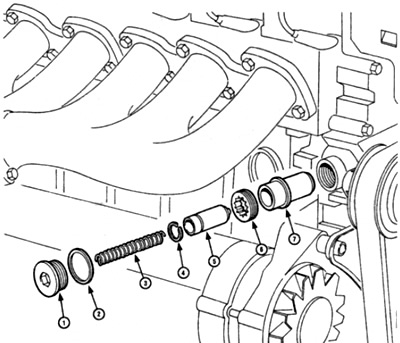
Pic. 8.3. Timing Chain Tensioner Parts
Warning: The cap nut is compressed by spring force. So be prepared for it to come off when the nut reaches the end of the thread.
4. Using the appropriate Allen wrench or a suitable hex wrench, unscrew the tensioner threaded ring and remove it from the body.
5. Remove the tensioner pusher/body assembly from its socket.
6. Press the tensioner pusher and circlip out of the tensioner housing (see fig. 8.6).
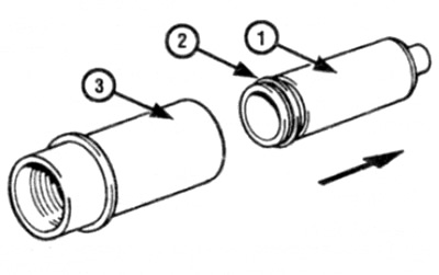
Pic. 8.6. Squeeze out the tensioner pusher (1) and retaining ring (2) from the tensioner (3) in the direction of the arrow
Examination
7. Thoroughly clean the tensioner parts and check the wear of the pusher and tensioner housing.
8. Check up a condition of a lock ring and a tensioner spring, and replace if necessary. If there is any doubt about the condition of the spring, replace it.
Installation
9. Insert the tensioner housing into the slot in the chain cover.
10. Screw the threaded ring into the body and tighten it to the required torque.
11. Push the pusher together with the retaining ring into the tensioner housing until the pusher reaches the stop in the tensioner housing. Remember that the smaller end of the pushrod is installed towards the tensioner rail.
12. Install the spring and new o-ring on the cover nut, then push the cover nut on and thread it onto the end of the tensioner body. Try not to nut "bitten".
13. Tighten the tensioner cover nut to the required torque.
14. Connect the negative battery terminal.
Camshaft sprocket
Removing
15. Remove the upper chain cover as described in paragraph 6.
16. Turn the crankshaft so that the piston of the 1st cylinder is set to the TDC position, making sure that the timing marks are aligned as described in paragraph 3.
17. Remove the camshaft timing chain tensioner as described earlier in this paragraph.
18. Using quick-drying paint or a scraper, mark the camshaft sprocket and corresponding drive chain link. Similarly, mark between the cake and camshaft sprocket.
19. Turn away three bolts of fastening of an asterisk of a cam-shaft.
20. Remove the sprocket from the camshaft on models with self-adjusting suspension along with the hydraulic pump driven bushing), remembering the installation method, and separate the sprocket from the chain. Maintain tension on the chain and support the chain at the top of the casing to prevent it from falling off the camshaft sprocket.
21. Remove the segment key from the end of the camshaft.
Examination
Note: During the production of cars, various modifications of the camshaft sprockets were made. If the sprocket needs to be replaced, we strongly recommend that you consult your Mercedes-Benz dealer.
22. Check sprocket teeth for wear. Each tooth forms a reverse letter "V". If they are worn, the stressed side of each tooth will be slightly concave when compared to the other side of the tooth (those. the teeth will look like a hook). If the teeth are worn, the sprocket should be replaced.
Installation
23. Where provided, install the key on the end of the camshaft.
24. Make sure that the timing marks remain aligned as described in paragraph 3. If a new sprocket is to be installed, transfer the alignment mark from the old sprocket to the new one.
25. Put the chain on the sprocket, matching the marks made before removal.
26. Attach the sprocket to the shaft, making sure that it is correctly installed, as it was before removal.
27. Install the sprocket mounting bolts and tighten them to the required torque, keeping the shaft from turning, as during removal.
28. Install the chain tensioner as described earlier in this paragraph.
29. Using a suitable wrench, turn the crankshaft at the crankshaft pulley/oscillation hub bolt two full turns and check that the timing marks remain aligned. If not, it is likely that the chain has moved one tooth. In this case, remove the sprocket and change the position of the chain.
30. Install the upper camshaft housing as described in paragraph 6.
Crankshaft sprocket
Note: To install the sprocket, it must be heated to approximately 50°C. Removing the sprocket in the described way involves the use of an electric portable grinder. to cut the chain link. Before doing work, purchase this machine as well as a new link. A puller may be required to remove the sprocket.
Removing
31. Remove the camshaft timing chain tensioner rail as described below.
32. Cover exposed parts on the pallet with clean rags.
33. Remove the oil pump drive chain tensioner rail and spring from the bracket on the cylinder block - note the orientation of the spring to reinstall correctly (see fig. 8.33). Remove bushing.
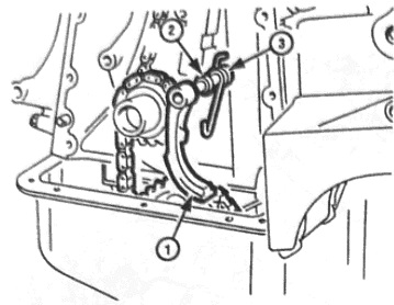
Pic. 8.33. Remove the oil pump drive chain tensioner rail from the bracket on the cylinder block (1), sleeve (2) and spring (3)
34. Using a grinder, grind the tabs on one of the oil pump drive chain links at the top of the sprocket. Be careful not to hit or damage the sprocket.
35. Hold the chain so it does not fall off the pump drive gear, then pull out the chain link plate and push the link into the reverse side of the chain.
36. Remove the rags, keeping the metal filings from falling into the pan.
37. Hold the chain on the oil pump drive gear with rope or wire.
38. Apply alignment marks on the camshaft sprocket and drive chain, then remove the camshaft drive chain from the sprocket.
39. Remove the crankshaft sprocket from the front of the shaft with a puller. You can use two large screwdrivers on each side of the sprocket as leverage. To correctly install the sprocket back, remember its position.
40. Remove the key from the shaft if it is loose.
Examination
41. For information on how to check the crankshaft sprocket, refer to item 22.
Installation
42. Install the slotted key on the end of the shaft.
43. If a new sprocket is to be installed, transfer the position mark from the old sprocket to the new one.
44. To install the sprocket on the crankshaft, it must be heated to approximately 50°C.
45. When the sprocket is approximately heated to the desired temperature (for a while, you can lower the star into very hot water), align the groove on the sprocket with the protrusion on the shaft, and slide the sprocket onto the end of the crankshaft. Make sure that the asterisk is located as it was before removal.
46. Pass the chain around the camshaft sprocket, making sure that the marks made on the sprocket and camshaft drive chain are aligned before removal.
47. Pass the chain around the crankshaft sprocket again, making sure that the marks made before removal on the sprocket and chain are aligned.
48. Place the two ends of the oil pump drive target on the crankshaft sprocket, then using a new link, connect the two ends of the chain. Install the link from the back of the chain and make sure the link is in place.
49. Install the link plate and secure the plate by flattening the ends of the link fingers. To perform this operation, there is a special device, however, satisfactory results can be achieved using a hammer and a metal bar attached to the back of the chain. Be careful not to damage the chain or sprocket.
50. Make sure the link is securely fastened without metal build-up or burr formation.
51. Install the drive chain tensioner rail bushing, spring and then tensioner rail. Check that the spring is oriented as noted before removal.
52. Install the camshaft timing chain tensioner as described later in this paragraph.
Guide rail
Removing
53. Turn the crankshaft so that the piston of the 1st cylinder is set to the TDC position, making sure that the timing marks are aligned as described in paragraph 3.
54. Remove the lower drive chain cover as described in paragraph 6.
55. Apply alignment marks to the chain and camshaft sprocket.
56. Remove the camshaft sprocket as described earlier in this paragraph.
57. Using a screwdriver, carefully release the clips and pry the outer part of the guide rail from the inner part (see fig. 8.57). Be careful as the latches break easily.
Pic. 8.57. Release the clips and separate the two halves of the guide rail (shown by arrows)
58. Pull the chain forward so that you can remove the inside of the rail from the bosses on the cylinder block.
Examination
59. Check for wear, cracks or damage to the rail. If found, replace. Check the inner-to-outer retainer and replace the assembly if it shows signs of wear or damage, or if the plastic has become round.
Installation
60. Push the inner rail section into place on the cylinder block brackets.
61. Put the chain in its place on the inside of the rail, then install the outer part and secure it with the retainers. Make sure the latches are secure and be careful not to break them.
62. Install the camshaft sprocket as previously described, making sure the marks made during removal match up.
63. Install the lower chain cover as described in paragraph 6.
Tensioner rail
Removing
64. Turn the crankshaft so that the piston of the 1st cylinder is set to the TDC position, making sure that the timing marks are aligned as described in paragraph 3.
65. Remove the lower casing of the camshaft drive chain. as described in paragraph 6.
66. Apply alignment marks to the camshaft drive chain and crankshaft sprocket.
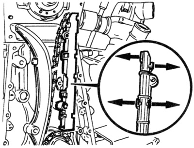
67. Turn the tensioner rail as far as necessary so that it can be removed from the axle (see fig. 8.67).
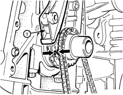
Pic. 8.67. Apply alignment marks (shown by arrows) on the chain and sprocket, then remove the tensioner rail
Examination
68. Check for wear, cracks or damage to the rail. If found, replace.
Installation
69. Push down on the rail, making sure it is correctly positioned over the axle.
70. Make sure that the alignment marks of the crankshaft and camshafts coincide with the position of the piston of the 1st cylinder at TDC, as described in paragraph 3.
71. Make sure that the marks on the chain and crankshaft sprocket, applied during removal, match.
72. Install the lower camshaft drive chain cover as described in paragraph 6.