



Removal
Note: This operation requires a hoist, winch, and sliding hammer and adapter. A new gasket is required for installation. New cylinder head bolts may be required.
1. Before removing the cylinder head, make sure the engine is cool. Note that the head is removed together with the intake and exhaust manifolds.
2. Disconnect the negative battery terminal.
3. Raise the hood to the fully open position as described in Chapter 11.
4. Drain the cooling system as described in Chapter 1A.
5. Remove the camshaft sprocket as described in paragraph 8.
6. Install a suitable bolt into the camshaft timing chain upper guide rail mounting pin (accessible from the front of the cylinder head).
7. Install the sliding hammer and the corresponding adapter with the bolt and use the hammer to pull out the installation pin of the rail (see fig. 10.7).
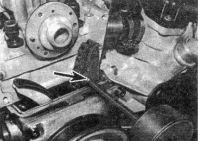
Fig. 10.7 Using a sliding hammer to remove the top guide rail locating pin
8. Loosen the bolt securing the dipstick tube bracket to the cylinder head.
9. Loosen the bolts and remove the two intake manifold support brackets (see fig. 10.9).
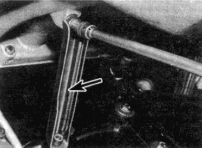
Fig. 10.9. Loosen the bolts and remove the intake manifold support brackets
10. Loosen the clamp securing the short water pump hose to the cylinder head (see fig. 10.10).
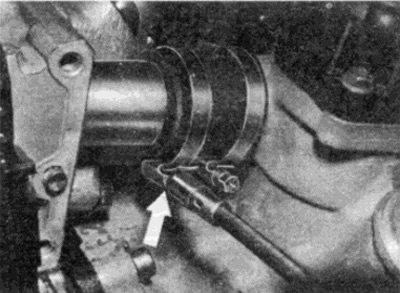
Fig. 10.10. Loosen the clamp (shown by arrow), securing the water pump hose to the cylinder head
11. Similarly, disconnect the interior heater return hose from the tube on the back of the cylinder head.
Material taken from a web resource (www.mercedesman.ru)
12. On models with an automatic transmission, unscrew the bolt securing the fluid level dipstick guide tube to the cylinder head (see fig. 10.12).
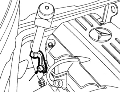
Fig. 10.12. Head of the mounting bolt (shown by arrow) fluid level dipstick to gear head
13. Depressurize the fuel system as described in Chapter 4, then unscrew the fittings and disconnect the supply and drain lines of the power supply, when unscrewing the fitting nut, hold the fitting on the pressure regulator. Prepare to drink gasoline and take adequate measures.
14. Disconnect the throttle cable from the linkage as described in Chapter 4.
15. On models with automatic transmission, disconnect the pressure control cable from the throttle linkage as described in Chapter 7.
16. Disconnect all electrical connectors on the cylinder head, remembering their location.
17. Release all harnesses from brackets and holders on the engine.
18. Disconnect the wire plugs and vacuum tube from the ignition control unit.
19. Loosen the mounting screw and disconnect the wires from the connector on the diagnostic socket (see fig. 10.19).
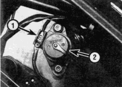
Fig. 10.19. Disconnect the wire from the connector (1) on the support of the diagnostic socket (2)
20. Remove the bolts and diagnostic socket, then disconnect the gray connector on the left side of the socket.
21. Disconnect the front sections of the exhaust system from the manifold as described in Chapter 4.
22. Make a final check that all relevant hoses and wires have been removed and do not interfere with the removal of the cylinder head.
23. Proceeding in the reverse order to that shown in Fig. 10.42, gradually loosen the cylinder head mounting bolts.
24. Loosen the cylinder head bolts.
25. Attach the hoist and winch to the rigging brackets on the cylinder head. Raise the hoist to lift the cylinder head.
26. Rock the cylinder head to remove it from the cylinder block and mounting keys. Do not use a lever between the mating surfaces of the head and cylinder block (see fig. 10.26).
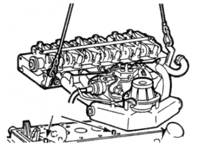
Fig. 10.26. Raising the cylinder head - the arrows indicate the mounting keys
27. Carefully lift the cylinder head, together with the manifolds, from the block and, maneuvering, pull the head out of the engine compartment.
28. Remove the cylinder head gasket.
Examination
29. Contact Chapter 2G for information on disassembling and assembling the cylinder head. If desired, the manifolds can be removed as described in Chapter 4.
30. Before installing the head, clean the mating surfaces of the head and cylinder block. Use a scraper to remove all traces of gasket and carbon deposits. Clean the piston crowns as well. Be careful with the aluminum cylinder head, as the soft metal is easily damaged. Make sure that no debris gets into the oil and water passages. Use tape and paper to cover the bolt holes, oil and water passages in the cylinder block. To prevent carbon deposits from getting into the gap between the piston and cylinder, apply a small amount of grease to the gap. After cleaning each piston, turn the crankshaft so that the piston moves down the cylinder bore. Then remove the grease and carbon deposits with a clean rag.
31. Check the block and cylinder head for chips, deep scratches or other damage. If they are very slight, they can be removed from the cylinder block using sandpaper. More serious damage can be corrected by grinding on a machine, however, this is a job for specialists.
32. If there is a suspicion of warpage of the cylinder head surface, use a metal ruler to check the surface distortion as described in Chapter 2G.
33. Clean the bolt holes in the cylinder block with an absorbent cloth or a thin cloth on a screwdriver. Make sure all oil and water is removed, otherwise the hydraulic pressure may cause the block to burst when tightening the bolts.
34. Check the bolt threads and the threads in the cylinder head for damage. If necessary, use a tap of the appropriate size to restore the threads in the block.
35. Manufacturers recommend checking the length of the cylinder head bolts to determine if replacement is necessary, however, some owners may choose to replace all bolts if desired.
36. Measure the length of each bolt from the base of the head to the end of the shaft (see fig. 11.36). If the bolt length exceeds the maximum permitted by technical specifications, the bolts must be replaced.
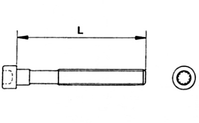
Fig. 10.36. Measuring the length of the cylinder head bolt
L maximum length = 108.4 mm
Installation
37. Where required, install manifolds as described in Chapter 4.
38. Check the alignment of the timing marks on the camshaft and crankshaft with the position of the piston of the 1st cylinder at TDC, as described in paragraph 3.
39. Install the gasket onto the keys in the cylinder block, checking that it is installed correctly.
40. Suspend the cylinder head using a hoist and winch, then lower the head onto the cylinder block.
41. Lubricate the threads and contact surfaces of the cylinder head bolts with oil, then insert the bolts into the cylinder block holes and tighten by hand.
42. Tighten the cylinder head bolts in the order shown in Fig. 10.42. Tighten the bolts in several steps as shown in Technical conditions — i.e. tighten all bolts to 1st degree torque, then tighten bolts to 2nd degree torque, etc.
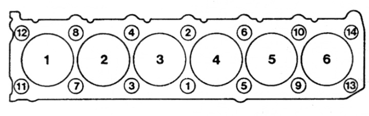
Fig. 10.42. Cylinder head bolt tightening sequence - 6-cylinder petrol engines
43. Connect the front sections of the exhaust system to the manifold as described in Chapter 4.
44. Reconnect all vacuum lines and wire connectors to their proper locations. Secure the engine wire harnesses with the appropriate holders and brackets.
45. On automatic transmission models, connect the pressure control cable to the throttle control lever as described in Chapter 7.
46. Connect the throttle cable to the throttle control lever as described in Chapter 4.
47. Connect the fuel lines and tighten the fittings.
48. Where required, install the automatic transmission fluid level dipstick guide tube mounting bolt to the cylinder head.
49. Connect the interior heater hose to the pipe on the back of the cylinder head and connect the cooling hose to the water pump.
50. Install the two intake manifold mounting brackets.
51. Tighten the bolt securing the dipstick tube bracket to the cylinder head.
52. Check that the camshaft timing chain guide rail is positioned correctly, then tap the rail installation rod into place using a hammer and drift. Make sure that the threaded end of the rod faces forward, i.e. after installing the rod, the threads should be visible.
53. Install the camshaft sprocket as described in paragraph 8.
54. Fill the cooling system as described in Chapter 1A.
55. Connect the negative terminal to the battery.