
Carburetor engines
1. Remove the air cleaner as described in Chapter 4, then check that the carburetor throttle lever rests on the idle speed screw. If not, follow these steps (see fig. 4.1):
- A) Start the engine.
- b) Pinch the throttle actuator vacuum hose so that the throttle lever rests on the speed adjustment screw x.x.
- V) Stop the engine.
Pic. 4.1. Pressure Control Cable Adjustment - Carburetor Models
A throttle lever
In Speed adjustment screw x.x.
With vacuum hose
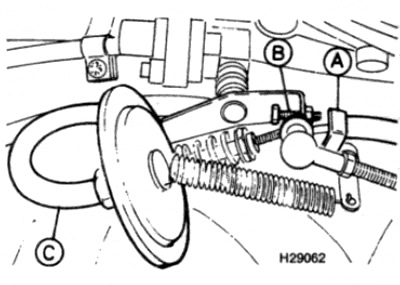
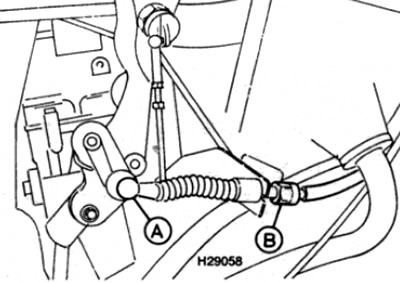
2. Disconnect the end of the pressure control cable from the ball joint on the throttle linkage.
3. Push the cable sheath back into the cable case (those. push it towards the gearbox), then pull it out again until you feel some resistance.
4. At the point where resistance begins to be felt, it is necessary to install the end of the cable on the ball joint of the linkage. If the cable is too long or too short. turn the case adjuster as far as necessary to easily install the cable end onto the ball joint (see fig. 4.4).
Pic. 4.4. Remove the end of the rope (1) with ball joint (2), then push it in the direction of the arrow. Turn the cable case adjuster if necessary (3) - carburettor models
5. When adjustment is complete, install the air cleaner.
4-cylinder fuel injected engines
Models with cable connection board
6. Remove the air cleaner as described in Chapter 4.
7. Loosen the clamp screw on the pressure control cable connection board (see fig. 4.7).
Pic. 4.7. Pressure Control Cable Adjustment - 4 Cylinder Fuel Injected Engines with Cable Interconnect Board
A Connection board
The screw clamp
8. Pull out the connection board, then push it back in until you feel a slight resistance, then tighten the clamp screw.
9. Install the air cleaner as described in Chapter 4.
Models with knurled adjusting wheel and pointer
10. Turn the adjusting wheel until there is approximately 1.0 mm play between the end of the cable and the bushing at the end of the adjuster.
11. Turn the adjusting wheel back until the pointer tip is exactly over the groove in the center of the adjusting wheel (see fig. 4.11).
Pic. 4.11. Pressure Control Cable Adjustment - 4 Cylinder Fuel Injected Engines with Knurled Adjustment Nut and Pointer
A Adjustment wheel
The bushing
The groove on the adjusting wheel is shown by an arrow
Models with Adjuster on Rope Case
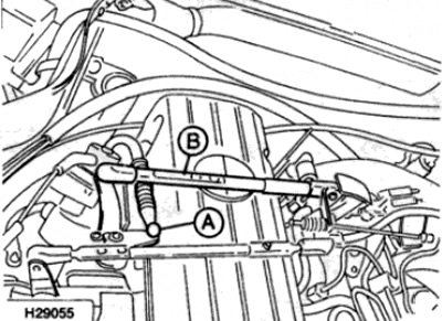
12. Disconnect the cable end from the ball joint on the linkage.
13. Pull on the cable to feel the resistance to movement.
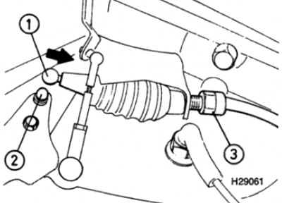
14. At the point where resistance begins to be felt, it is necessary to install the end of the cable on the ball joint of the linkage. If the cable is too long or too short, turn the case adjuster as far as necessary to easily install the cable end onto the ball joint (see fig. 4.14).
Pic. 4.14. Pressure Control Cable Adjustment - 4 Cylinder Fuel Injected Engines with Adjuster on Cable Case
A Rope end
B Cable case adjuster
6-cylinder petrol engines
Models with Adjuster on Rope Case
15. Follow the steps described in p.p. 12-14.
Models with knurled adjusting wheel and pointer
16. Follow the steps described in p.p. 10 and 11.
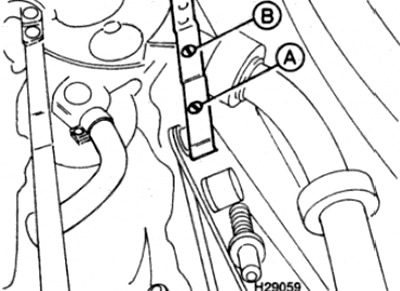
Pic. 4.18. Pressure Control Cable Adjustment - Diesel Engines
A End of pressure control cable
B Throttle lever connection plate
19. Tighten the pressure control cable until you feel a slight resistance to movement.
20. At the point where resistance begins to be felt, it is necessary to install the end of the cable on the ball joint of the linkage. If necessary, adjust the length of the connecting plate so that the end of the cable can be easily put on the ball joint.