
Removing
1. Raise the hood and place a thin sheet of metal (approximately 300 mm area) behind the bulkhead of the engine compartment to protect the insulation of the bulkhead during subsequent work.
2. Disconnect the negative battery terminal.
3. On models equipped with an auxiliary heater, be careful not to damage the cooling hose at the rear of the engine compartment when performing the following steps. Remove the transmission oil dipstick tube bolts from the cylinder head.
4. Disconnect the transmission pressure control cable from the throttle linkage on the intake manifold.
5. Apply the parking brake, then raise the vehicle and jack it up (see "Vehicle lifting and jacking up"). The vehicle must be raised high enough to allow the gearbox to be pulled out from under it. Where fitted, remove the underbody protection as described in Chapter 11.
6. Where required, remove the cross member bolts (gearbox located in front of the pallet) and take it off. Dispose of mounting bolts as new ones must be used for installation.
7. Place a suitable container under the main transmission drain, then remove the plug and drain the transmission fluid (see chapter 1).
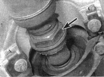
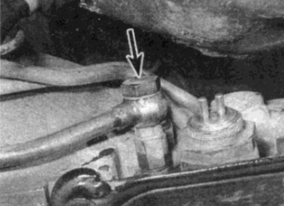
8. Move a container under the torque converter hole in the gearbox housing. Using a wrench, turn the crankshaft by the shaft pulley / vibration damper hub until the torque converter drain plug is visible in the hole (see fig. 6.8). Unscrew the plug and drain the fluid from the torque converter.
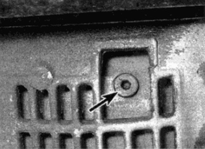
Pic. 6.8. Torque converter drain plug (shown by arrow), aligned with the hole in the gearbox
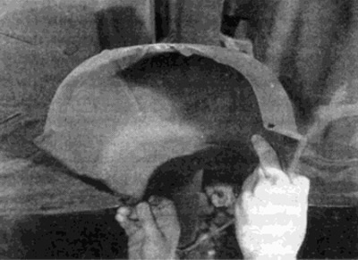
9. Pry off the plastic plug from the gearbox bell housing to expose the bolts securing the torque converter to the drive faceplate (see fig. 6.9).
Pic. 6.9. Pry off the plastic plug to expose the bolts securing the torque converter to the drive faceplate
10. Turn away six bolts of fastening of the hydrotransformer to a leading faceplate, turning a cranked shaft.
11. Position a small block of wood between the engine pan and welded the cross piece on the bottom of the car.
12. Remove the complete exhaust system as described in Chapter 4.
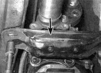
13. Where provided, unscrew the bolts and remove the heat shields from the bottom of the car to gain access to the intermediate driveshaft bearing (see fig. 6.13).
Pic. 6.13. Remove the heat shield to gain access to the driveshaft
14. Turn away from the bottom (under the driveshaft) and from the gearbox mounting bolts and remove the exhaust system support brackets (see fig. 6.14). Where provided, unfasten the wires from the bracket on the gearbox.
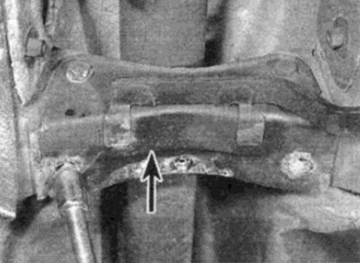
Pic. 6.14. Loosen the bolts and remove the support bracket (shown by arrow) from the bottom of the car
15. Disconnect the cardan shaft from the gearbox flange as described in Chapter 8.
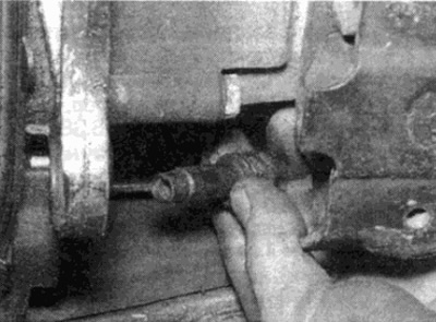
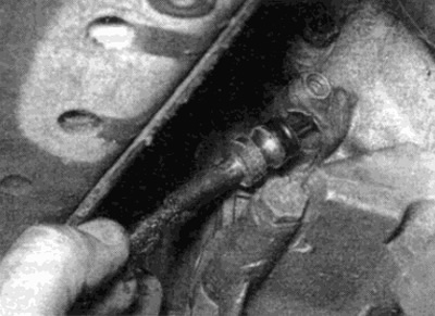
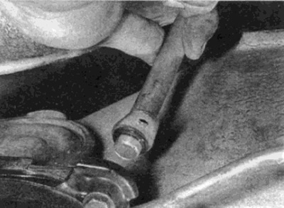
16. Loosen the clamp nut on the propshaft intermediate bearing, then loosen (but don't shoot) intermediate bearing nuts and push the shaft back as far as possible (see fig. 6.16).
Pic. 6.16. Loosen propshaft clamp nut (shown by arrow)
17. Support the transmission with a wheel jack and an intermediate piece of wood.
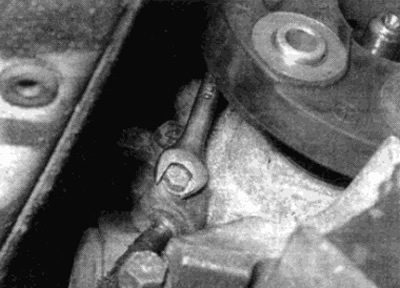
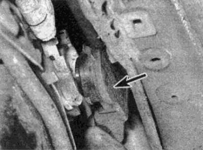
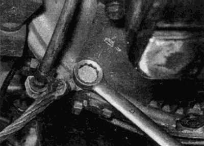
18. Turn away bolts of a back arm of the power unit on a transmission and the bottom of the car and remove an arm (see fig. 16.18).
Pic. 6.18. Turn away bolts and remove an arm of a back support of the power unit (shown by arrow)
19. Disconnect the wire plug from the low shift solenoid in the rear right corner of the transmission (see fig. 6.19).
Pic. 6.19. Disconnect the plug from the downshift solenoid
20. Loosen the pinch bolt and pull the speedometer cable out of the gearbox as described in Chapter 12 (see fig. 6.20, a, b). Where provided, loosen the clamps securing the cable to the gearbox.
Pic. 6.20 a. Loosen the pinch bolt...
Pic. 6.20 b....and pull out the speedometer cable
21. Release the starter interlock switch/reversing light switch connector from the retainer. Carefully pry off the switch connector with a screwdriver (see fig. 6.21).
Pic. 6.21. Disconnect the starter interlock switch/reversing light switch connector (shown by arrow)
22. Where provided, unscrew the knurled retaining ring and disconnect the wire plug on the left side of the transmission (see fig. 6.22).
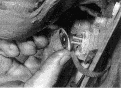
Pic. 6.22. Unscrew the retaining knurled ring and disconnect the wire plug
23. Disconnect all remaining electrical connectors on the gearbox. Release the wires from the clamps and / or brackets on the gearbox housing and move the wires away from the gearbox.
24. Disconnect the vacuum tubes from the vacuum assembly on the left side of the gearbox (see fig. 6.24). Disconnect any remaining vacuum tubes. Release all tubing from clamps and/or brackets on transaxle case and move tubing away from transaxle. Please note that on some models it may be necessary to disconnect certain pipes from the intake manifold in order to be able to lead them away from the gearbox.
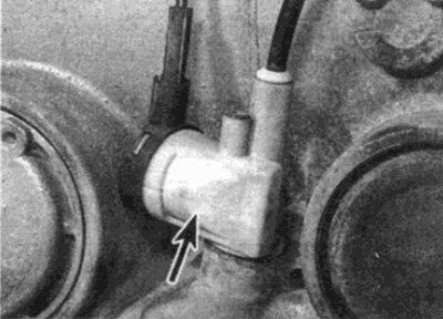
Pic. 6.24. Disconnect the vacuum lines from the vacuum assembly (shown by arrow)
25. Remove the metal clips and disconnect the shift rod from the gear selection lever on the gearbox and the shift lever, if necessary referring to paragraph 3. Remove shift rod.
26. Turn away bolts of unions and disconnect inlet and return pipes of the heat exchanger of liquid of a transmission from a box (see fig. 6.26). Remove the o-rings and plug or cover the open ends of the pipes and gearbox to keep out dirt.
Pic. 6.26. Disconnect the transmission fluid heat exchanger tubes
27. Turn away bolts of arms of tubes of the heat exchanger of liquid of a transmission from a transmission and the engine and move tubes that they did not interfere with removal of a transmission.
28. Pull the retainer up and remove the fluid level probe in the gearbox.
29. Remove the clamp bolt securing the dipstick guide tube/filler tube to the transmission case. Where provided, remove the gearbox-to-engine bolt that holds the dipstick tube bracket to the gearbox bell housing. Pull the dipstick tube / filler tube out of the gearbox (see fig. 6.29).
Pic. 6.29. Removing the filler tube / filler tube
30. Remove the starter as described in Chapter 5 A.
31. Make sure the gearbox is securely supported, then lower the power unit as far as possible so that the engine rests on a block of wood inserted between the pan and cross member. Be careful not to hit the hydraulic pipes and other parts at the rear of the engine compartment against the bulkhead as the cylinder head may be pushing against the bulkhead.
32. Turn away all bolts of fastening of a box to the engine, leaving on one bolt from each party of a gear box. Access to the upper bolts is very difficult even when the node is hung. Multiple ratchet wrench extensions may be required. On some engines (especially on 6-cylinder) the top bolt cannot be unscrewed from below and can be more easily accessed with an open-end wrench from the right side after following these steps:
- A) Unscrew the heat shields from the area around the steering box to gain access to the exhaust mounting nuts.
- b) Loosen the mounting nuts and remove from the cylinder head (rear) exhaust manifold, remove gasket.
Note the location of the ground rail and all brackets that are held in place by the gearbox-to-engine bolts (see fig. 6.32).
Pic. 6.32. Unscrew the bolts securing the engine to the gearbox, remembering the location of the ground bus
33. When the upper bolts of the gearbox to the engine are removed, lift the gearbox so that the power unit is horizontal.
34. On models with diesel engines, when pulling out the gearbox, it is necessary to hold the torque converter, otherwise there is a risk of falling out of the case (other models have a plastic retainer built into the bell housing). It is best to hold the torque converter by inserting a suitable rod through the hole in the bell housing into the torque converter drain port (see point 8).
35. Remove the remaining two mounting bolts, then slide the box back as far as possible and lower it down with a jack. Be careful not to let the torque converter fall out.
Warning: The gearbox is heavy!
36. To remove the torque converter, follow these steps (see fig. 6.36):
- A) Hold the gearbox upright on wooden blocks with the bell housing and torque converter mounted vertically.
- b) Using an Allen key 8.0 mm. turn the plastic torque converter retaining rod a quarter of a turn counterclockwise, then remove the retaining rod (on models with diesel engines, remove the rod inserted when removing the gearbox).
- V) Attach the two lifting handles to the converter using the long bolts in the mounting holes on the faceplate. Using the handles, pull the hydra transformer out of the gearbox. You can screw in the two long bolt holes securing the hydraulic transformer to the faceplate and use them to lift the torque converter out of the gearbox. Be prepared that some of the liquid may spill.
- G) Store the torque converter in a safe place where it cannot be damaged.
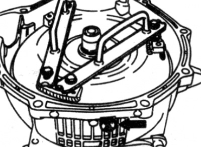
Pic. 6.36. Handles for lifting the torque converter. The arrow shows the holding rod
Installation
37. Where required, install the torque converter as follows:
- A) Apply some grease to the torque converter drive flange. Motykot lubricant is recommended.
- b) Using two bolts, install the torque converter in place. Push the torque converter in as far as possible to make sure which teeth are engaged with the transmission input shaft.
- V) Where provided, install the plastic retaining rod and turn it a quarter of a turn clockwise (on diesel models, align the torque converter locking rod with the drain hole in the transformer as when removing).
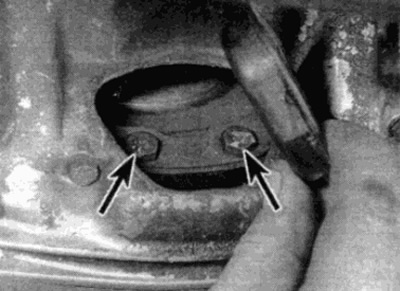
- G) Rotate the torque converter so that two holes are located on the bottom of the base of the bell-shaped gearbox housing for the bolts securing the torque converter to the drive faceplate.
38. Support the transmission with a wheel jack and a wooden spacer, as in removal. Then, raise the box to the required height under the vehicle.
39. Move the gearbox forward so that the bell housing is pressed against the engine.
40. Install and tighten the mounting bolts, making sure the ground rail and all brackets are in place.
41. Further actions are the opposite of those for withdrawal, taking into account the following points:
- A) When connecting the transmission fluid heat exchanger tubes, use new O-rings.
- b) Connect the propeller shaft as described in Chapter 8.
- V) Where required, tighten all fasteners to the required torque.
- G) Check that all wires and vacuum hoses are properly connected and routed in the same way as before removal.
- d) Install the exhaust system as described in Chapter 4.
- e) Fill the gearbox with the required fluid as described in Chapter 1.
- and) When finished, check pressure control cable adjustment as described in paragraph 4.