



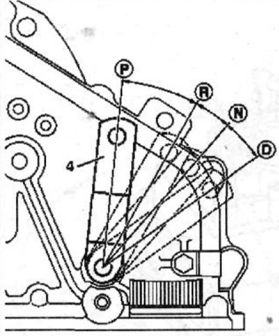
5.0 Gearbox Control Lever Positions
4 - gear shift fork rod
P - position of the lever when parking
R - reverse gear
N - neutral gear
D - movement
The gearbox control lever can be moved to other positions by moving it in the transverse direction.
Removal
The procedure for removing and installing an automatic transmission is the same as for a manual transmission.
1. Unscrew the drain plug from the gearbox housing and drain the transmission oil, first placing a container under the gearbox to collect the oil.
Please note: There is no drain hole on the torque converter.
Caution! If the transmission fluid has a burnt smell or contains carbon particles, the lines leading to the oil cooler and the oil cooler itself should be flushed. If metal particles are found in the transmission fluid, the torque converter should be removed and the lines and oil cooler should also be flushed. Remaining metal particles may cause damage to the transmission.
2. Lower the engine on the front beam (see the relevant chapter).
Attention! To lift the engine, three chains must be passed through the right and left sides of the engine and oil pan. The chains must be positioned as vertically as possible, which is possible with the help of an appropriate frame (see illustration 5.0a).
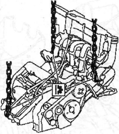
5.0a Fastening the power unit to the crane beam.
3. Raise the power unit with a suitable overhead crane to relieve the load on the suspension supports.
4. Unscrew bolts 1 and 2 (see illustration).
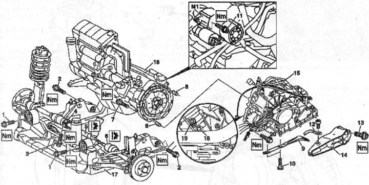
5.4 Unscrew bolts 1 and 2
3 - intermediate shaft support/bearing mounting bolt
4 - intermediate shaft support/bearing
5 - right drive shaft
6 - left drive shaft
7 - engine and gearbox mounting bolt
8 - centering bushings
9 - catalytic converter bracket
10 - catalytic converter bracket mounting bolt
11 - starter mounting bolt
12 - ground wire (-)
13 - gearbox support mounting bolt
14 - gearbox support
15 - gearbox
16 - engine
17 - front beam of the power unit suspension
18 - bolt
19 - plastic plug
20 - bracket
M1 - starter
5. Using a suitable screwdriver, pry the tail of the left half-shaft 6 out of the gearbox (see illustration 5.4).
6. Unscrew bolts 3 securing the support/support bearing 4 of the intermediate shaft to the cylinder block (see illustration 5.4).
7. Using a suitable screwdriver, pry the intermediate shaft 5 tailpiece of the right half-shaft out of the gearbox (see illustration 5.4).
8. Carefully lift engine 16 together with gearbox 15 and remove them from the front beam 17, carefully removing the tailpieces of the left half-axle, as well as the intermediate shaft from the gearbox (see illustration 5.4),
Check the condition of the drive shaft retaining rings and replace them with new ones if damaged.
9. Unscrew bolts 10 securing bracket 9 of the catalytic converter to the gearbox (see illustration 5.4).
10. Disconnect wire 12 "ground" (-) from support 14 of the gearbox (see illustration 5.4).
11. Unscrew the bolts of bracket 20, to which the oil pipes are attached, from support 14 and (see illustration 5.4).
12. Unscrew bolts 13 and disconnect support 14 (see illustration 5.4).
13. Unscrew bolts 11 and remove starter M1 (see illustration 5.4).
14. Unscrew bolts 18 that secure the torque converter.
Before unscrewing the bolts, remove the plastic plugs 19 (see illustration 5.4).
15. Unscrew bolts 7 and separate engine 16 and gearbox 15 (see illustration 5.4).
Caution! Do not lose the centering bushings 8 (see illustration 5.4). Before connecting the power unit, make sure that the centering bushings (2 pcs.) are in place.
16. Remove the torque converter.
Installation of the automatic transmission is carried out in the reverse order of removal.
17. Fill the gearbox with transmission oil.