
2. Setting the piston of the 1st cylinder to the TDC position is an important condition for many procedures, such as replacing the drive chain and replacing the camshaft.
3. Determine the position of the terminal of the high-voltage wire of the 1st cylinder on the cover of the ignition distributor. If the terminal is not marked, trace the high voltage wire from the spark plug of the first cylinder to the cover (No. 1 cylinder is located on the drive chain side of the engine].
4. Remove the camshaft cover as described in paragraph 4.
5. Using a suitable socket on the vibration damper hub bolt/crankshaft pulley, turn the crankshaft clockwise until the following marks are aligned (see fig. 3.5, a, b).
- A) TDC label "ABOUT"/"T") on the crankshaft pulley is aligned with the edge of the crankshaft position sensor support bracket.
- b) Rod or TDC hole (depending on engine type) on the flange at the front of the camshaft is aligned with the lip on the front camshaft bearing cap.
- V) The ignition distributor slider is aligned with the mark on the outer rim of the distributor housing (you may have to remove the distributor cap to see the mark - see Chapter 5B).
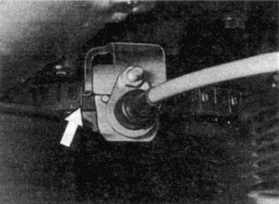
Pic. 3.5, a. TDC label ("ABOUT"/"T") (shown by arrow) on crankshaft pulley/vibration damper aligned with edge of crankshaft position sensor support bracket
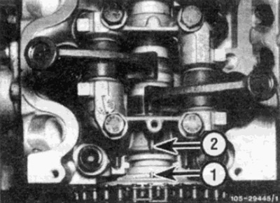
Pic. 3.5b. TDC rod (1) on the camshaft aligned with the ledge (2) on the bearing cap
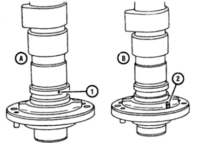
Pic. 3.5, c. TDC marks on the camshaft
A Later shaft models with TDC hole (1)
B Early shaft models with TDC pin (2)
6. When the marks are aligned, as described in paragraph 5, the piston of the 1st cylinder will be in the TDC position. If the camshaft drive chain is to be removed, do not rotate the crankshaft until the chain is reinstalled.