



Contents: Removal ↡ Installation ↡
Caution! When installing the lower cover, it is necessary to use sealant and a new O-ring for the coolant pipe. It is also advisable to replace the front crankshaft O-ring.
Removal
Unscrewing the bolts and bracket from the drive chain cover
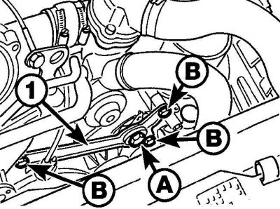
After loosening the center bolt (A) of the auxiliary drive belt tensioner, unscrew the three bolts (B) and rotate the bracket (1) away from the drive chain cover.
Radiator Fan Bracket and Crankshaft Angle Sensor Fastening Elements
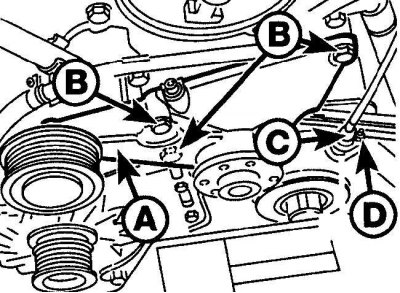
1 – radiator fan bracket; 2 – bolts; 3 – crankshaft angle sensor; 4 – nut
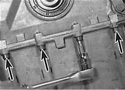
Location of oil pan to lower timing chain cover bolts
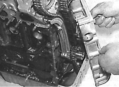
Removal the lower drive chain cover
1. Remove the ground cable from the battery.
2. Open the hood and place it in a vertical position.
3. Remove the engine splash shield.
4. Remove the air filter.
5. Remove the fan impeller and hydraulic coupling.
6. Remove the bolt securing the air intake pipe to the front body panel.
7. Remove the auxiliary drive belt.
8. Remove the bolts and pulleys of the auxiliary drive belt.
9. Remove the crankshaft pulley/vibration damper and hub.
10. Remove the upper drive chain cover.
11. Loosen the center bolt securing the auxiliary drive belt tensioner, then remove the three bolts and rotate the bracket away from the drive chain cover (see Fig. Unscrewing the bolts and bracket from the drive chain cover).
12. Remove the two bolts securing the power steering pump to the bracket and rotate the pump away from the engine.
13. If present, remove the air pump and move it to the side without disconnecting the hoses from it.
14. Unscrew the bolts and remove the radiator fan bracket (see fig. Fastening elements of the radiator fan bracket and crankshaft angle sensor).
15. Unscrew the nut and remove the crankshaft angle sensor from the bracket on the timing chain cover. Release the sensor wiring from the mounting brackets and move the sensor to the side.
16. Disconnect the electrical wires from the generator.
17. Unscrew the four bolts securing the generator bracket to the engine and remove the generator together with the bracket.
18. Working underneath the vehicle, remove the bolts securing the oil pan to the lower timing chain cover (see Fig. Location of oil pan to lower drive chain cover bolts). Mark the location of the bolts as they are different sizes.
19. Remove the remaining lower timing chain cover mounting bolts, noting their locations as different sized bolts are used.
20. Remove the lower timing chain cover (see Fig. Removing the lower cover of the drive chain).
Caution: When removing the lower timing chain cover, be careful not to damage the oil pan gasket.
Installation
Applying sealant to the mating surfaces of the cylinder block and the lower timing chain cover
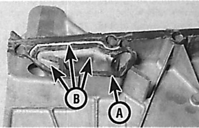
After applying sealant to the mating surfaces of the cylinder block and lower timing chain cover (A), check that no sealant enters the oil supply chamber passages to the timing chain tensioner (B).
Replacing the sealing ring in the hole for the lower mounting bolt of the radiator fan bracket
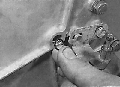
1. Clean the mating surfaces of the lower timing chain cover, engine block and upper timing chain cover.
2. Check the condition of the oil pan gasket. If the gasket is damaged, replace it.
3. Clean the sealing ring seat.
4. Install a new sealing ring into the cover seat.
5. To avoid damaging the working edges of the crankshaft sealing ring when installing the lower timing chain cover, wrap the front end of the crankshaft with adhesive tape.
6. Apply a thin layer of sealant to the mating surfaces of the cylinder block and timing chain cover. Be careful not to let any sealant get into the oil supply chamber to the timing chain tensioner in the cover or into the oil passages (see Fig. Applying sealant to the mating surfaces of the cylinder block and the lower cover of the drive chain).
7. Lubricate the crankshaft seal lips with clean engine oil and install the lower timing chain cover onto the cylinder block.
8. Install the bolts securing the oil pan to the timing chain cover and tighten them to the specified torque.
9. Install the remaining timing chain cover mounting bolts and tighten them to the specified torque.
10. Replace the sealing ring installed in the hole for the lower mounting bolt of the radiator fan bracket in the timing chain cover (see Fig. Replacing the sealing ring in the hole for the lower mounting bolt of the radiator fan bracket).
11. Remove the adhesive tape from the front end of the crankshaft.
12. Install the generator and connect the wires to it.
13. Install the crankshaft angle sensor to the bracket on the timing chain cover and secure it with the nut.
Caution: When installing a new lower timing chain cover, the position of the crankshaft angle sensor must be checked and, if necessary, adjusted.
14. Install the radiator fan bracket and secure it with bolts.
15. If available, install an air pump.
16. Install the power steering pump into place and secure with bolts.
17. Apply sealant to both sides of the holes for the drive chain cover mounting bolt in the auxiliary drive belt tensioner bracket.
18. Rotate the auxiliary drive belt tensioner bracket into place and secure with bolts.
19. Install the upper drive chain cover.
20. Install the crankshaft pulley/vibration damper and hub.
21. Install and bolt the auxiliary drive belt pulleys.
22. Install the auxiliary drive belt.
23. Install and secure the air intake tube with a bolt.
24. Install the hydraulic clutch and radiator fan impeller.
25. Install the air filter.
26. Install the lower engine splash shield.
27. Fill the cooling system with coolant.
28. Check the level and, if necessary, add engine oil to the engine.