
Basic provisions
1. The timing gear is part of the camshaft bearing caps. The cams are mounted on separate short shafts that are seated in the camshaft bearing caps. Each cover has one exhaust and one intake cam.
2. Hydraulic tappets are mounted on the cams and supplied with oil through holes in the cams.
Removing
3. Remove the air cleaner as described in Chapter 4.
4. Remove the camshaft cover as described in paragraph 4.
5. Remove the camshaft sprocket as described in paragraph 8.
6. On models with adjustable valve clearances, loosen locknuts and back out cam adjusting screws as far as possible.
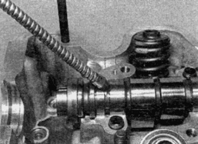
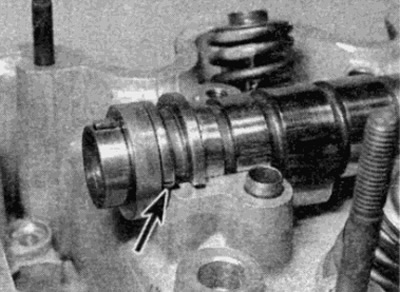
7. Check for identification marks on cams and bearing caps. The caps are usually numbered 1 to 4 counting from the sprocket side on the exhaust manifold side of the bearing caps (see fig. 10.7). The corresponding mark is cast on the cylinder head under the camshaft. If any of the caps is not numbered, make the appropriate marks with a center punch.
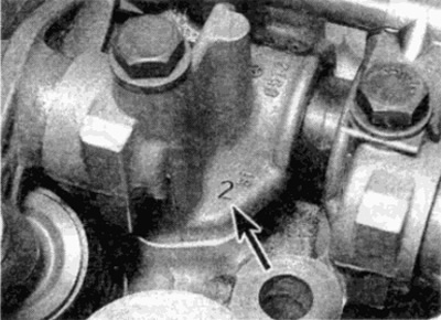
Pic. 10.7. Camshaft bearing cap identification mark (shown by arrow)
8. Gradually, acting in a diagonal sequence, unscrew the bolts of the camshaft bearing caps. Note the location of the oil spray tube brackets.
9. Pull up the oil spray tube (see fig. 10.9).
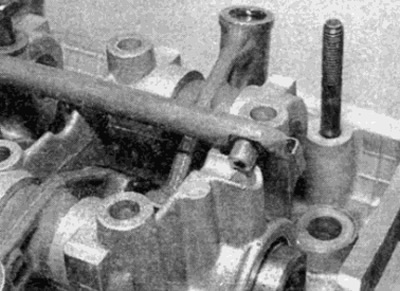
Pic. 10.9. Raise the oil spray pipe
10. Remove bearing cap/cam assemblies (see fig. 10.10). Note that the lids are mounted on pins - if they are stuck, lightly tap the lids with a mallet.
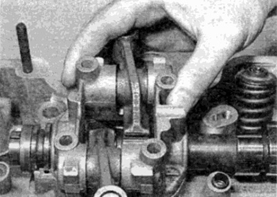
Pic. 10.10. Removing Bearing Cap/Cam Assemblies
11. On models with hydraulic lifters, remove the contact pads of the lifters from the valve stems, keeping them in strict order (see fig. 10.11). You can't swap parts.
Pic. 10.11. Remove valve lifter pads
12. Carefully remove the shaft from the cylinder head.
On models with hydraulic lifters, store contact pads in an eight-compartment split box labeled 1 to 4 for intake valves and 1 to 4 for exhaust.
Disassembly, inspection and assembly
Camshaft
13. Check the bearings and shaft cams for signs of wear, scoring, deep scratches or pitting. If found, the shaft must be replaced. Any damage of this nature indicates a blockage of the lubrication channel either in the cylinder head, or in the cam assembly, or in the oil spray tube. To find out the reason, you need to carefully check the details. When replacing the camshaft, the cams also change at the same time.
Cam drive gear
14. With the camshaft bearing caps removed, the cams can be removed from the caps by pulling out the short cam shafts. Before removing the cams, check for the presence of identification marks and, if any, apply it (designate cams 1 to 4 for intake valves and 1 to 4 for exhaust). Do not swap parts. Pay attention to how the cams are mounted on the shafts.
15. To remove the cam shafts, it is best to use a proprietary tool, consisting of a sliding hammer and a special adapter. An alternative method is to screw in a suitable long bot (M8) with a washer into the cam shaft, then to pull out the shaft, it is necessary to hit the washer with a hammer. Be careful not to damage parts (see fig. 10.15). With the shaft removed, the cam can be removed. Parts must be stored in a strict order, for example in a box divided into compartments.
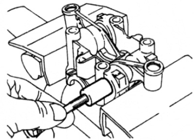
Pic. 10.15. Using an M8 bolt to pull the cam shaft out of the bearing cover
16. On models with adjustable valve clearances, check for wear on the adjuster tips that contact the valve stems. Check how the cams are installed on their shafts. If visible wear or damage is found, replace the parts as a set.
17. On models with hydraulic tappets, check for wear on the contact pads of the pushers. Check how the cams are installed on their shafts. If visible wear or damage is found, it is recommended to replace the parts as a set.
18. Thoroughly clean the parts before installation.
19. Lubricate the mating surfaces of the cams and shaft, then following the notes below, install the shaft and cam onto the appropriate bearing cover.
- A) If working parts are installed, make sure they are installed in their original places.
- b) Make sure each pusher fits properly onto the shaft as noted prior to removal.
- V) Make sure the camshaft bearing cap bolt groove on each shaft is aligned with the camshaft bearing cap bolt hole.
- G) If you do not have a branded tool, use the long bolt and washer that was used during removal to install the cam shaft into the cover.
Hydraulic valve lifters
20. To remove the follower from the cam, insert a suitable drift into the hole in the top of the cam and push the follower out of the cam.
21. Remove the shim from the pusher housing in the cam (see fig. 10.21).
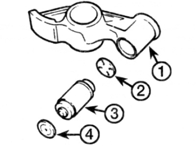
Pic. 10.21. Valve lifter/cam assembly
1 Cam
2 Adjusting washer
3 Valve tappet
4 Contact pad
22. Store the valve lifters and washers in a strict order so that they can be installed in their places.
23. Check up wear of pushers of valves and washers. If wear or damage is found, replace them.
24. The design of hydraulic tappets is such that the amount of play or clearance they can compensate for is limited. Basically, this is determined by the small size of the nodes. To keep the gap at a minimum level and to enable the pushers to work within operating limits, shims of various thicknesses are installed.
25. Under normal conditions, the tappets automatically adjust to provide the required clearance between the cam and the valve stem.
26. However, if the parts are significantly worn or after replacing the camshaft, cams, valves or tappets themselves, the valve assembly becomes noisy in operation, the gaps may have gone beyond automatic compensation. In this case, it is necessary to replace the adjusting washer with a different size.
27. To determine the required thickness of the shim, a special indicator device and clamp are required. Have the work done by a Mercedes-Benz dealer.
28. It is recommended to install valve lifters with the cams already mounted on the cam shafts. This will reduce installation time and reduce the possibility of valve lifters draining oil if prepared as described below.
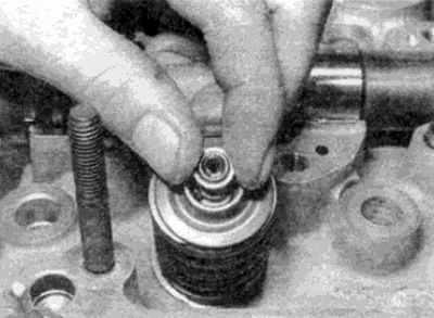
29. Before installation, each valve must be filled with oil. To do this, hold the assembly upright and fill the chamber with clean engine oil. Using a piece of thin wire inserted through the chamber, press down on the ball valve so that the oil can drain into the working chamber (see fig. 10.29). At the same time, push the pusher up to the stop. Repeat these steps several times until the oil stops leaving the working chamber.
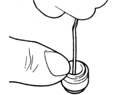
Pic. 10.29. Press down on the pusher ball valve with a piece of thin wire
30. Install the shim onto the cam body with the oil notches facing the pushrod, then insert the pushrod. Press the pusher until it contacts the circlip. The bearing cap/cam assembly can then be installed on the motor.
Installation
31. Lubricate the camshaft and bearings in the bearing caps and cylinder head with clean engine oil, then lay the camshaft in place on the cylinder head. Rotate the camshaft so that the alignment mark is aligned with the upper plane of the cylinder head - see paragraph 3 (see fig. 10.31 a. b).
Pic. 10.31 a. Thoroughly lubricate the camshaft
Pic. 10.31 b. Align the camshaft groove (shown by arrow) with the upper plane of the cylinders
32. On models with hydraulic tappets, install the tappet contact pads on the appropriate valve stems.
33. On models with adjustable valve clearances, make sure the adjusting screws are fully turned out.
34. Install the bearing caps in place with the identification numbers on the exhaust manifold side and the mating surfaces of the oil squirt tube brackets facing back.
35. Position the oil supply tube on top of the bearing caps, making sure the oil holes in the tube line up with the corresponding holes in the bearing caps.
36. On adjustable clearance models, install the cover bolts and tighten them gradually, in a diagonal sequence, with force. required specifications.
37. On models with hydraulic valve lifters, do the following:
- A) Turn the camshaft so that the cams of the shaft of the first cylinder are facing down, i.e. from the cam - so that the pusher is unloaded when the cover bolt is tightened.
- b) Install the 1st bearing cover bolts and progressively tighten the bolts to the correct torque.
- V) Repeat steps a) and b) for bearing cap No. 3. No. 4 and finally No. 2 by turning the camshaft so that when the bolts are tightened, the corresponding cams are facing down.
38. If it has not already been done, rotate the camshaft so that the alignment mark is aligned with the upper plane of the cylinder head. Then check that the crankshaft alignment mark is aligned with the TDC position of the 1st cylinder (see paragraph 3).
39. Install the camshaft sprocket as described in paragraph 8.
40. On adjustable valve models, adjust clearances as described in Chapter 1A.
41. Install the camshaft cover as described in paragraph 4.
42. Install the air cleaner.