
Tensioner
Note: A new tensioner cover nut o-ring will be required during installation.
Removing
1. Disconnect the negative battery terminal.
2. Remove the accessory drive belt as described in Chapter 1A.
3. For better access, remove the alternator as described in Chapter 5.
4. Working from the right side of the engine, unscrew the tensioner cover nut and remove the spring and O-ring (see fig. 8.4, a, b).
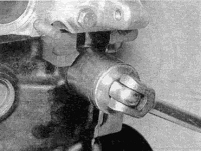
Pic. 8.4, a. Loosen the chain tensioner cap nut...
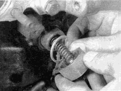
Pic. 8.4, b....and remove the spring and o-ring
Warning. The cover nut is pressed by the spring force. So be prepared for it to come off when the nut reaches the thread.
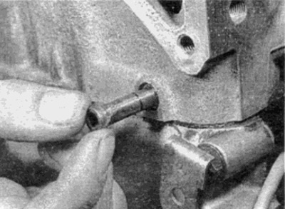
5. Using the appropriate Allen wrench or a suitable hex wrench, unscrew the tensioner housing and remove it from the cylinder block (see fig. 8.5).
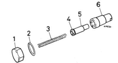
Pic. 8.5. Timing Chain Tensioner Parts
1 Cover nut
2 O-ring
3 spring
4 Retaining ring
5 Pusher
6 Tensioner housing
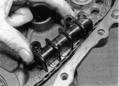
6. Squeeze out a pusher and a lock ring from the case of a tensioner (see fig. 8.6).
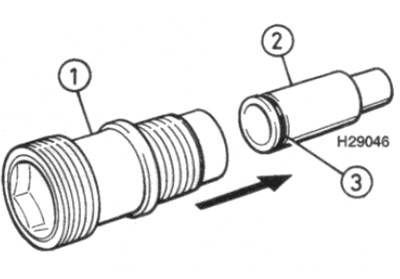
Pic. 8.6. Squeeze the tensioner pushrod out of the housing
1 Tensioner housing
2 Pusher
3 Retaining ring
Examination
7. Thoroughly clean the tensioner parts and check the wear of the pusher and tensioner housing.
8. Check up a condition of a lock ring and a tensioner spring, and replace if necessary. If there is any doubt about the condition of the spring, replace it.
Installation
9. Screw the tensioner housing into the cylinder block and tighten it to the required torque.
10. Push the pusher together with the retaining ring into the tensioner body until the pusher reaches the stop in the body (see fig. 8.10). Remember that the smaller end of the pusher rests against the tensioner beam.
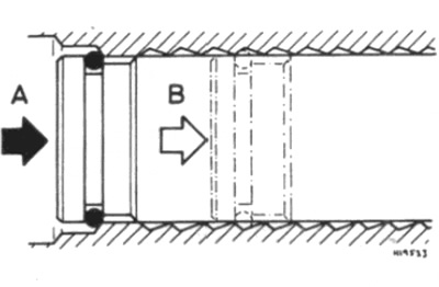
Pic. 8.10. Tensioner tappet position
A Initial stop when installing the pusher
B Direction of removal and installation of pusher
11. Install the spring and new o-ring on the cover nut, then push the cover nut on and thread it onto the end of the tensioner body. Try not to nut "bitten".
12. Tighten the tensioner cover nut to the required torque.
13. Install the generator (see chapter 5).
14. Install the accessory drive belt as described in Chapter 1A.
15. Connect the negative battery terminal.
Camshaft sprocket
Removing
16. Remove the air cleaner as described in Chapter 4.
17. Remove the radiator fan blades and shroud as described in Chapter 3.
18. Where installed, remove suspension leveling system hydraulic pump as described in Chapter 10. Recall that the pump can be moved to the side without disconnecting the hydraulic pipes.
19. Remove the camshaft cover as described in paragraph 4.
20. Rotate the crankshaft. so that the piston of the 1st cylinder is set to the TDC position, making sure that the timing marks are aligned as described in paragraph 3.
21. Remove the camshaft timing chain tensioner as described earlier in this paragraph.
22. Using quick-drying paint or a scraper, mark the camshaft sprocket and corresponding drive chain link.
23. While holding the camshaft from turning with a wrench on the flats of the camshaft flange on the reverse side, unscrew the camshaft sprocket bolt (see fig. 8.23, a, b).
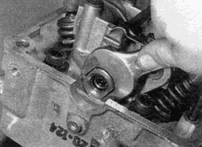
Fig.8.23, a. Hold the camshaft with a wrench on the flats of the flange on the back side...
Pic. 8.23.6....and unscrew the sprocket bolt and remove the washer
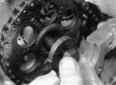
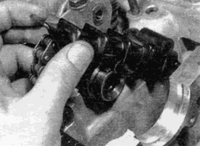
24. Remove the sprocket from the camshaft (on self-adjusting suspension models together with hydraulic pump driven bushing), remembering the installation method and separate the sprocket from the chain (see fig. 8.24). Maintain tension on the chain and support the chain at the top of the casing to prevent it from falling off the camshaft sprocket or auxiliary shaft sprockets.
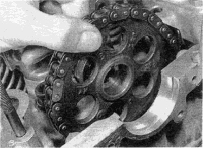
Pic. 8.24. Remove the sprocket from the camshaft
25. Remove the segment key and, where required, the sleeve from the end of the camshaft if they are loose.
Examination
26. Check sprocket teeth for wear. Each tooth forms a reverse V. If worn, the stressed side of each tooth will be slightly concave when compared to the other side of the tooth (those. the teeth will look like a hook). If the teeth are worn, the sprocket should be replaced.
Installation
27. Where provided, install the bushing and key on the end of the camshaft.
28. Make sure the timing marks remain aligned as described in paragraph 3. If a new sprocket is to be installed, transfer the alignment mark from the old sprocket to the new one.
29. Put the chain on the sprocket, matching the marks made before removal.
30. Attach the sprocket to the shaft, making sure that it is correctly installed, as it was before removal. Note that on single row target models, the large sprocket guard hub must face towards the collar on the shaft (those. first, the sprocket is installed on the camshaft side with a protective hub) and on models with two-row chain, the curved side of the teeth must face the shoulder (those. first, the sprocket is installed with the curved side of the teeth). Where provided, also install the self-adjusting suspension hydraulic pump driven bush.
31. Install the sprocket mounting bolt and washer. Then, tighten the bolt to the required torque while holding the shaft from turning, as when removing.
32. Install the chain tensioner as described earlier in this paragraph.
33. Using a suitable wrench, turn the crankshaft at the crankshaft pulley/oscillation hub bolt two full turns and check that the timing marks remain aligned. If not, it is likely that the chain has moved one tooth. In this case, remove the sprocket and reposition the target,
34. Install the camshaft cover as described in paragraph 4.
35. Where provided, install the self-adjusting suspension hydraulic pump as described in Chapter 10.
36. Install the radiator fan blades and shroud as described in Chapter 3.
37. Install the air cleaner as described in Chapter 4.
Crankshaft sprocket
Removing
Note: A puller may be required to remove the sprocket.
38. Remove the camshaft drive chain cover as described in paragraph 6.
39. Using quick-drying paint or a scraper, mark the camshaft sprocket and corresponding drive chain link.
40. Remove the camshaft sprocket as previously described.
41. On later models, to disconnect the chain from the crankshaft sprocket, it may be necessary to remove the chain tensioner rail. Where provided, remove the tensioner rail as described below.
42. Remove the oil pump drive bush from the crankshaft (see fig. 8.42). If the seal is tight, it can be removed with the crankshaft sprocket later.
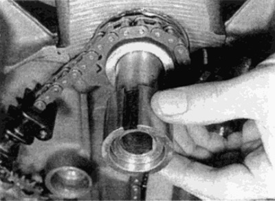
Pic. 8.42. Removal from the crankshaft of the split drive bushing of the oil pump
43. Disconnect the chain from the crankshaft sprocket.
44. Remove the crankshaft sprocket from the front of the shaft. If the sprocket is tight, you can use two large screwdrivers on each side of the sprocket as leverage. You can remove the star (and, where required, the oil pump drive bushing) using a puller. To correctly install the sprocket back, remember its position.
45. Remove the key from the shaft if it is loose.
Examination
46. For information on checking the sprocket, see step 26.
47. Check up wear of a leading surface of a leading cuff of the oil pump. If severe wear is evident, the sprocket must be replaced.
Installation
48. Install the slotted key on the end of the shaft.
49. If a new sprocket is to be installed, transfer the position mark from the old sprocket to the new one.
50. Hammer the sprocket onto the shaft using a metal pipe. Make sure the sprocket is aligned with the key or dowel pin if used,
51. Install the oil pump drive collar.
52. Put the chain on the crankshaft sprocket, making sure that the marks made when removing the sprocket are aligned.
53. Where required, install the camshaft timing chain tensioner rail as described later in this paragraph.
54. Install the camshaft sprocket as previously described.
55. Install the chain guard as described in paragraph 6.
Auxiliary shaft sprocket
56. The asterisk is an integral part of the auxiliary shaft. Removal and installation of the auxiliary shaft are described in paragraph 9.
Guide rails
57. Remove the chain cover as described in paragraph 6.
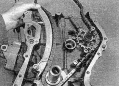
58. Pull the chain guides off the retainers (see fig. 8.58, a, b).
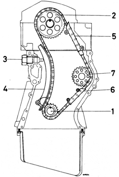
Pic. 8.58 a. Camshaft Drive Chain - Single Row Chain Models
1 crankshaft sprocket
2 Camshaft sprocket
3 Chain tensioner
4 Tensioner rail
5 Top guide rail
6 Bottom guide rail
7 Auxiliary shaft sprocket
Pic. 8.58b. Removing the Lower Guide Rail - Single Row Chain Models
59. Check for wear, cracks or damage to the rail. If found, replace.
60. To install, simply push the guide rail into place, making sure it is secure.
61. Install the chain guard as described in paragraph 6.
Bottom Guide Rail - Double Row Chain Models
62. Remove the auxiliary shaft as described in paragraph 9.
63. Remove the chain from the crankshaft sprocket.
64. Remove the crankshaft sprocket forward from the end of the shaft to provide enough clearance to remove the guide rail. If the sprocket is tight, you can use two large screwdrivers on each side of the sprocket as leverage. You can remove the star (and, where required, the oil pump drive bushing) using a puller.
65. Remove the chain guide from the clips.
66. Check for wear, cracks or damage to the rail. If found, replace.
67. To install, simply push the guide rail into place, making sure it is securely seated.
68. Hammer the sprocket onto the shaft using a metal pipe. Make sure the sprocket is aligned with the key or dowel pin if used.
69. Install the oil pump drive collar.
70. Put the chain on the crankshaft sprocket, making sure that the marks made when removing the sprocket are aligned.
71. Install the auxiliary shaft as described in paragraph 9.
Top guide rail
Note: This operation will require a puller and an adapter. When installing the guide rail, sealant must be applied to the ends of the retainers.
72. Remove the camshaft sprocket as previously described.
73. Screw a suitable bolt into one of the guide rail pins (accessible from the front of the cylinder head).
74. Install the puller and bolt adapter, and use the puller to pull out the rail pin (see fig. 8.74, a, b).
Pic. 8.74. A. Use a puller, an adapter and a suitable bolt...
Pic. 8.74b....to pull out the top guide rail pin
75. Repeat for the remaining pin, being careful not to let the rail slide down the chain into the shroud when the pin is removed.
76. Remove the guide rail from the cylinder head (see fig. 8.76).
Pic. 8.76. Removing the upper guide rail from the cylinder head
77. Check for wear, cracks or damage to the rail. If found, replace.
78. Position the rail in place in the shroud, then position the pins in the holes in the cylinder head and hammer them in to hold the rail.
79. Apply sealant to the outer collar of each pin where it fits into the cylinder head, then drive the pins all the way into the cylinder head. Check that the latch on the rail aligns with the groove in the top locating pin.
80. Install the camshaft sprocket as described earlier in this paragraph.
Tensioner Rail - Models with Single Row Timing Chain
Removing
81. Remove the chain cover as described in paragraph 6.
82. Remove the camshaft sprocket as described earlier in this paragraph.
83. Turn the tensioner rail as far as necessary so that the axle can be removed (see fig. 8.83).
Pic. 8.83. Removing the Tensioner Rail - Single Row Camshaft Timing Chain Models
Examination
84. Check for wear, cracks or damage to the rail. If found, replace.
Installation
85. Push down on the rail, making sure it is correctly positioned over the axle.
86. Install the camshaft sprocket as previously described.
87. Install the camshaft drive chain cover as described in paragraph 6.
Tensioner Rail - Dual Row Camshaft Timing Chain Models
Removing
Note: You will need a puller and adapter to complete the operation. Installation will require a new tensioner rail axle.
88. Remove the chain cover as described in paragraph 6.
89. Remove the camshaft sprocket as previously described.
90. Drill a small hole (approximately 5.8 mm) at the end of the tensioner rail axis, then with the appropriate tap (MB) cut a thread about 10 mm deep from the end of the axle.
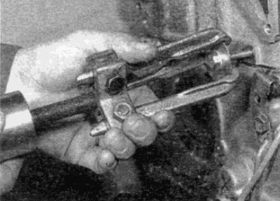
91. Screw a small bolt into the end of the axle, then install a puller with an adapter on the bolt and pull the axle out (see fig. 8.91).
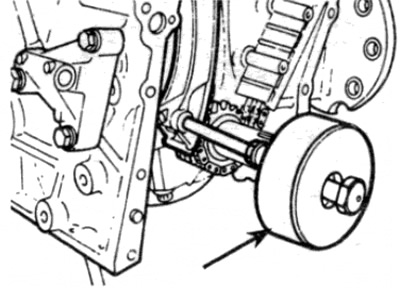
Pic. 8.91. Using a Puller (shown by arrow) for removing the tensioner rail axle - models with a double row drive chain
92. Remove the tensioner rail.
Examination
93. Check for excessive wear, cracks or damage to the rail. If found, replace.
Installation
94. Bring the rail to the installation site, then, using a hammer and drift, drive in a new axle.
95. Install the camshaft sprocket as previously described.
96. Install the camshaft drive chain cover as described in paragraph 6.