
Removing
Note: New flywheel/drive plate mounting bolts may be required for installation.
1. Remove the motor as described in Chapter 2D or gearbox as described in Chapter 7.
2. Where required, remove the clutch as described in Chapter 6.
3. To loosen the mounting bolts, the flywheel / drive faceplate must be locked. This can be done by attaching a gear fixture (engaging with the teeth of the starter ring) on the cylinder head using one of the engine/gearbox mounting bolts.
4. Gradually turn away bolts of fastening, then remove a flywheel / a leading faceplate from a cranked shaft. Please note that the flywheel is located on the keys. On models with automatic transmission, remove the spacers.
Examination
5. If the teeth on the flywheel starter ring gear are severely worn or some of the teeth are missing, the drive faceplate assembly must be replaced as the ring gear is welded to the faceplate on automatic transmission models.
6. On models with a manual transmission, it is possible to replace the ring gear. This work is best done at a service station, since the temperature to which the crown must be heated is very critical. If it is not maintained, the strength of the teeth may be impaired.
7. On manual transmission models, if the surface of the flywheel that is in contact with the clutch disc has deep nicks, cracks, or other damage, the flywheel must be replaced. However, it is possible to grind the surface of the flywheel; consult an engine remanufacturer.
8. Manufacturers recommend checking the length of flywheel bolts to determine if replacement is necessary, however, some owners may want to replace all bolts if desired.
9. Measure the length of each bolt from the base of the head to the end of the shaft (see fig. 14.9). If the bolt length exceeds the maximum specification, the bolts must be replaced.
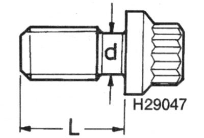
Pic. 14.9. Flywheel/faceplate bolt measurement
d Minimum diameter = 8.0 mm
L Max length = 22.5mm
10. Similarly, measure the diameter of the bolt on the shank between the base of the bolt head and the start of the thread. If the diameter is less than the minimum allowable, the bolt must also be replaced.
Installation
11. Begin installation by cleaning the mating surfaces of the crankshaft and flywheel/drive faceplate.
12. Attach the flywheel to the crankshaft, placing it on the keys (on models with automatic transmission, make sure the spacer plates are in place), then install the mounting bolts (see p.p. 8-10, inclusive).
13. Stop the flywheel using the method used for removal, then gradually tighten the mounting bolts in a diagonal pattern. Tighten the bolts in the multiple steps given in the Specification - i.e. tighten all bolts to 1st stage torque, then tighten bolts to 2nd stage torque, etc.
14. Where required, install the clutch as described in Chapter 6.
15. Install the motor as described in Chapter 2D or gearbox as described in Chapter 7.