
General provisions
1. The power unit is mounted on three supports, one on each side of the engine and one at the rear below the gearbox (see fig. 17.1). Additionally, on some models, an engine limiter is installed in front of the engine between the sump and the cross member. Some models are also equipped with an engine mount damper mounted on the engine on the left.
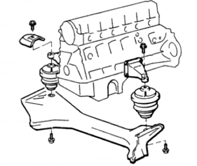
Pic. 17.1. Front engine mounts
Examination
2. Raise the front of the vehicle and support it on jack stands for better access (see "Vehicle lifting and jacking up").
3. Check up a condition of rubber of support. If cracks, hardening, or separation from the metal are found at any point, the support should be replaced.
4. Make sure all support fasteners are securely tightened.
5. Using a large screwdriver or metal bar, lever out the support to check for wear. If this does not work, ask the assistant to move the engine back and forth or side to side, while observing whether there is free play in the supports. Despite. that a small play is present even in new parts, increased wear will be noticeable. If play is detected, first check the reliability of the fastening of the support. and then, if necessary, replace worn parts.
6. The engine travel stop is adjustable and when checking the engine mounts, check the travel stop adjustment as described below.
7. To check the condition of the engine mount shock absorber, remove the shock absorber as described in this paragraph. Then move the damper piston to a full stroke and then to a short stroke. In both cases, a constant and even resistance should be felt. If the resistance is uneven, abrupt, or there is visible damage or wear to the shock absorber, it should be replaced.
Replacement
Left and right engine mounts
8. If not already done, raise the front of the vehicle and support it on jack stands (see "Vehicle lifting and jacking up").
9. Support the engine either by hanging it with a hoist and winch, or by substituting a jack with a wooden spacer from below under the pallet. Before starting work, make sure the engine is securely supported.
10. Remove the motor shield from below as described in Chapter 11.
11. Where required, loosen and remove the adjusting bolt from the engine travel stop (see par. 30).
12. On models equipped with an engine mount shock absorber, remove the two bolts securing the lower end of the shock absorber to the front cross member.
13. Turn away bolts of fastening of the left and right support of the engine to a forward cross beam.
14. Unfasten the radiator fan shroud and place it on top of the fan blades as described in Chapter 3.
15. Connect the hoist and winch to the front engine rigging bracket, then carefully raise the hoist to raise the engine.
16. Where required, remove the heat shield from the right engine mount.
17. Turn away bolts of fastening of support of the engine to arms of support, then take support.
18. If desired, then you can unscrew the support brackets from the cylinder block.
19. Installation is carried out in the reverse order, taking into account the following points:
- A) Tighten all fasteners to the required torque.
- b) When installing an engine travel stop, adjust the stop as described below.
Rear support of the power unit
20. If not already done, raise the front of the vehicle and support it on jack stands (see "Vehicle lifting and jacking up")
21. If necessary, remove the engine shield as described in Chapter 11.
22. Support the gearbox with a jack with a wooden spacer.
23. Where provided, remove the foot adjuster screw.
24. Turn away bolts of fastening of a basic crossbar to the bottom of a body, then turn away two bolts fastening a crossbar to a support and remove a crossbar.
25. Turn away a nut fixing a support to a transmission, and remove a support.
26. Installation is carried out in the reverse order, taking into account the following points:
- A) Tighten all fasteners to the required torque.
- b) Before tightening the foot adjuster screw, adjust the stopper as described below.
Engine travel limiter
27. If not already done, raise the front of the car and place on supports (see "Vehicle lifting and jacking up").
28. If necessary, remove the engine shield as described in Chapter 11.
29. Turn the steering wheel all the way to either side.
30. Loosen and remove the engine travel stop adjuster bolt
31. Turn away two bolts of fastening and remove the limiter of movement.
32. Begin installation by putting the travel stop in place and tightening the mounting bolts to the required torque.
33. Lower the car to the ground so that it rests on the wheels.
34. Install the adjusting bolt, but do not tighten it at this stage.
35. Completely loosen the adjusting screw of the rear support of the power unit.
36. To install the limiter rubber, it is best to use a special tool from Mercedes-Benz. However, two strips of metal plate approximately 3.0 mm thick can be accommodated. Slide a fixture or metal strips on each side of the stopper elastic (see fig. 17.36).
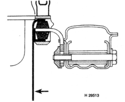
Pic. 17.36. Using a special tool (shown by arrow) for adjusting the motor travel limiter
37. Grab the engine and move the power unit by hand, swinging it from side 8 to side.
38. Tighten the rear support adjustment screw to specification.
39. Tighten the travel stop adjustment bolt to specification.
40. Where provided, install the engine shield.
Engine mount damper
41. The mount shock absorber is bolted between the engine support bracket and the front cross member.
42. Remove the two bolts securing the lower end of the shock absorber to the front transverse beam (see fig. 17.42).
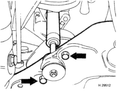
Pic. 17.42. Bolts of fastening of the shock-absorber of a support of the engine to a cross beam (shown by arrows)
43. Turn away a bolt of fastening of the top end of the shock-absorber on an arm of a support of the engine.
44. Squeeze the stand as far as necessary so that it can be pulled out of the support bracket.
45. If the shock absorber bands are removed from the shock absorber, note their location and orientation so that they can be reinstalled correctly.
46. Installation is carried out in the reverse order.