
Removing
Note: Installation will require a new gasket and may require new cylinder head bolts - see text. A new gasket comes with a sealing strip - do not remove the strip until you are installing the gasket.
1. Before removing the cylinder head, make sure the engine is cool. Please note that the head is removed together with the intake and exhaust manifolds.
2. Disconnect the negative battery terminal.
3. Raise the hood to the fully open position as described in Chapter 11.
4. Drain the cooling system as described in Chapter 1A.
5. Remove the air cleaner as described in Chapter 4.
6. Remove the sprocket and upper camshaft drive chain guide rail as described in paragraph 8.
7. Remove the accessory drive belt as described in Chapter 1A.
8. Disconnect the exhaust pipes from the exhaust manifold as described in Chapter 4.
9. Remove the dipstick guide tube nut from the exhaust manifold and remove the dipstick. Plug the dipstick tube. so that dirt does not get inside.
10. Disconnect the throttle cable from the linkage and remove it from the work area as described in Chapter 4.
11. Turn away bolts and remove a basic rack from an inlet collector. On carbureted engines, remove the single bolt holding the strut to the manifold. On fuel injected models, remove the two bolts and, working from below the manifold, disengage the throttle return spring (see fig. 11.11).
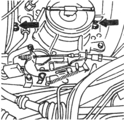
Pic. 11.11. Intake manifold support bolts (shown by arrows) - fuel injected engine
12. Disconnect the cooling hoses in front and behind the cylinder head (see fig. 11.12).
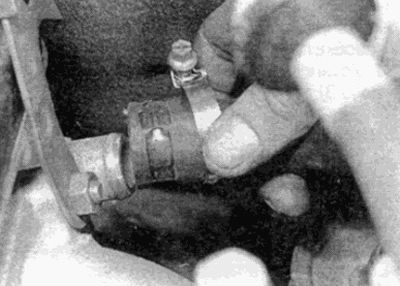
Pic. 11.12. Disconnecting the interior heater hose from the cylinder head
13. Disconnect the plug connectors from the switches and sensors mounted on the cylinder head and intake manifold / carburetor (depending on the model), remembering their location (see fig. 11.13).
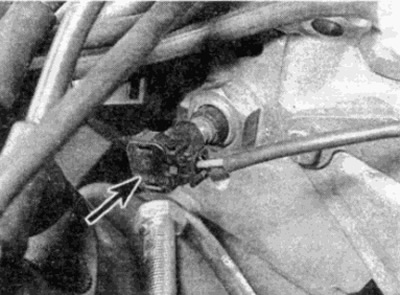
Pic. 11.13. Disconnecting the coolant temperature sensor connector (shown by arrow)
14. Similarly, disconnect the vacuum hoses from the vacuum valves attached to the cylinder head and intake manifold/carburetor (depending on the model).
15. Turn away a nut of the union and disconnect a vacuum hose of the brake booster from an inlet collector.
16. On models with fuel injection, depressurize the power system as described in Chapter 4.
17. Disconnect the supply and return pipes from the carburetor or from the fuel pressure regulator and fuel distributor (on models with fuel injection). Where necessary, hold the fittings while loosening the nuts. Plug or cover the open ends of the pipes and fittings to reduce the leakage of gasoline and the ingress of dirt.
18. On models with air conditioning, unscrew the bolts and remove the air conditioning tube bracket from the cylinder head.
19. On models with automatic transmission, disconnect the pressure control cable from the throttle linkage as described in Chapter 7B. Turn out from a head of cylinders a bolt of fastening of a tube of a dipstick of a liquid in transmissions.
20. Loosen the water pump bypass hose clamp on the thermostat housing.
21. Disconnect the upper radiator hose from the thermostat housing.
22. Where it is provided, turn away bolts and remove a tube of the EGR system. which connects the EGR valve to the intake manifold.
23. Where provided, check the parts of the emission control system and disconnect the relevant hoses, turn out the valves, etc., so that the cylinder head can be removed. Remember the location and routing of all hoses - this will help with assembly.
24. Final check that all required hoses, tubes and wires are disconnected (brackets / clamps unscrewed) and do not interfere with the removal of the cylinder head.
25. Working from the drive chain housing on top of the cylinder head, remove the three bolts securing the cylinder head to the drive chain housing (see fig. 11.25).
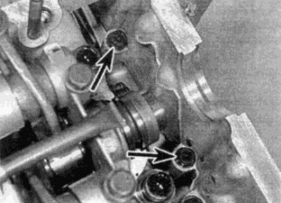
Pic. 11.25. Two of the three bolts securing the drive chain cover to the cylinder head (shown by arrows)
26. Gradually, acting in the reverse order shown in fig. 11.44, loosen the cylinder head bolts (see fig. 11.26).
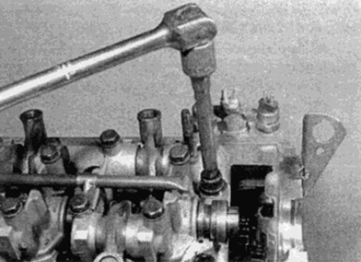
Pic. 11.26. Loosening the cylinder head bolt
27. Turn away bolts of a head of cylinders.
28. Slide the head off the cylinder block and dowel pins by rocking it. Do not use a lever between the mating surfaces of the head and cylinder block, as this may damage the surface.
29. It is best to lift the cylinder head off the block with a helper - be careful as the head is heavy.
30. Remove the cylinder head gasket.
Examination
31. Refer to Chapter 2D for information on disassembling and assembling the cylinder head. If desired, the manifolds can be removed as described in a Chapter 4.
32. Before installing the head, it is necessary to clean the mating surfaces of the head and cylinder block. Use a scraper to remove all traces of gasket and carbon deposits. Also clean the piston bottoms. Be careful with an aluminum cylinder head as the soft metal is easily damaged. Make sure that the fragments do not fall into the oil and water channels. Using adhesive tape and paper, close the bolt holes, oil and water channels in the cylinder block. Apply a small amount of grease to the gap to keep carbon deposits from entering the gap between the piston and cylinder. After cleaning each piston, rotate the crankshaft so that the piston moves down the cylinder bore. After that, use a clean rag to remove grease and soot.
33. Check up whether on the block and a head of cylinders of chips, deep scratches or other damages. If they are very weak, they can be removed from the cylinder block with sandpaper. More serious damage can be repaired by grinding on the machine, however, this work is for specialists.
34. If there is suspicion of warping of the surface of the cylinder head, use a metal ruler to check the curvature of the surface, as described in Chapter 2D.
35. Clean the bolt holes in the cylinder block with an absorbent cloth or thin cloth on a screwdriver. Make sure that all oil and water is removed, otherwise the block may be torn by hydraulic pressure when tightening the bolts,
36. Check whether the threads of the bolts and the threads in the cylinder head are damaged. If necessary. use an appropriately sized tap to re-thread the block.
37. Manufacturers recommend checking the length of the cylinder head bolts to determine if replacement is necessary; however, some owners may choose to replace all bolts if desired.
38. Measure the length of each bolt from the base of the head to the end of the shaft (see fig. 11.38). If the bolt length exceeds the maximum specification, the bolts must be replaced.
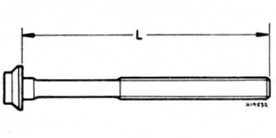
Pic. 11.38. Measuring the length of the cylinder head bolt
L maximum allowable length = 122.0 mm
Installation
Note: A new cylinder head gasket will be required during installation. A new gasket is shipped unopened - do not remove the packaging until the gasket is installed.
39. Where required, install manifolds as described in Chapter 4.
40. Check the coincidence of the alignment marks of the camshaft and crankshaft with the position of the piston of the 1st cylinder in the BMT, as described in paragraph 3.
41. Install the gasket on the keys in the cylinder block, making sure it is installed correctly.
42. Lower the cylinder head onto the block.
43. Lubricate the threads and contact surfaces of the cylinder head bolts with oil, then insert the bolts into the holes in the cylinder block and tighten by hand.
44. Tighten bolts of a head of cylinders in the order specified in fig. 11.44. Tighten the bolts in the multiple steps specified in the Specification - i.e. tighten all bolts to 1st stage torque, then tighten bolts to 2nd stage torque, etc.
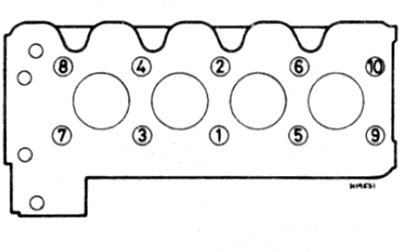
Pic. 11.44. Cylinder Head Bolt Tightening Sequence - 4-Cylinder Gasoline Engines
45. Install and tighten the three bolts securing the cylinder head to the drive chain housing.
46. Where provided, connect all emission control hoses to the cylinder head and/or install any removed parts that facilitate removal of the cylinder head. Check that the hoses are positioned and routed as they were prior to removal.
47. Where provided, install the EGR pipe that connects the EGR valve to the intake manifold.
48. Connect the upper radiator hose to the thermostat housing.
49. Connect the water pump bypass hose to the thermostat housing and tighten the clamp.
50. On models with an automatic transmission install a bolt of fastening of a tube of a dipstick of level of a liquid to a head of cylinders. Connect and adjust the pressure control cable as described in Chapter 7B.
51. On models with air conditioning, tighten the bolts securing the air conditioning tube bracket to the cylinder head.
52. Connect the supply and return fuel lines.
53. Connect the brake booster hose and tighten the union nut.
54. Connect all vacuum lines and electrical connectors.
55. Connect the cooling hoses in front and behind the cylinder head.
56. Establish a rack of fastening on an inlet manifold.
57. Connect and. if necessary, adjust the throttle cable as described in chapter 4.
58. Install the dipstick guide tube nut, then insert the dipstick.
59. Connect the front exhaust pipes to the exhaust manifold as described in chapter 4.
60. Install the accessory drive belt as described in Chapter 1A.
61. Install the upper drive chain guide rail and camshaft sprocket as described in paragraph 8.
62. Install the air cleaner.
63. Finally check that all parts are installed and all hoses, tubes and connectors are properly connected.
64. Fill the cooling system as described in Chapter 1A.
65. Connect the negative battery terminal, then start the engine and check for leaks.