
Removing
1. Disconnect the negative battery terminal.
2. Refer to Chapter 1A and drain the coolant.
3. Remove the carburetor as described in paragraph 10.
4. Disconnect the vacuum hose of the brake booster from the manifold - unscrew the bypass bolt and remove the washers (see fig. 11.4).
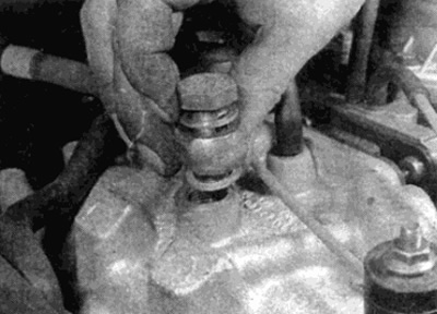
Pic. 11.4. Disconnect the brake booster vacuum hose from the intake manifold
5. Disconnect the vacuum hoses for the crankcase emission control system, automatic transmission, central locking and exhaust gas recirculation system from the intake manifold (EGR, where it is installed). Make a note of where each hose is connected to avoid confusion during reassembly.
6. Loosen the clamps and remove the cooling hoses from the nozzles on the intake manifold.
7. Where required, release wire harnesses from holders. Disconnect the intake manifold heater wire plug from the block - refer to Chapter 12.
8. Turn away bolts of fastening and remove a rack of fastening of an inlet collector.
9. Where required, remove the bolts and remove the throttle linkage mounting bracket from the cylinder head. Move it to the side.
10. Turn away on a head of cylinders a bolt of fastening of an arm for lifting of the engine (see fig. 11.10).
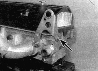
Pic. 11.10. Remove the bolt (shown by arrow) engine mount bracket
11. Loosen and remove the mounting nuts, then remove the engine lift bracket and intake manifold. Remove the pad.
Installation
12. Thoroughly clean the mating surfaces of the cylinder head and intake manifold - remove all traces of the old gasket. Be careful not to scratch or scuff the surfaces as this will create shadows. Before proceeding further, use a metal ruler to check the warping of both surfaces - for more information, see Chapter 2 Part D.
13. Position the new gasket on the cylinder head studs, then guide the manifold to the installation site.
14. The rest of the installation process is carried out in the reverse order of removal. Consider the following points:
- A) Tighten the manifold mounting nuts to the required torque.
- b) Fill the cooling system.
- V) Connect the wire plug to the manifold heater.
- G) Upon completion, check and, if necessary, adjust the idle speed. and CO content as described in Chapter 1A.