
Basic information
1. Before disassembling the carburetor, make sure that the ignition timing is set correctly. Spark plugs must be clean and their spark gap properly adjusted. The damper actuators must be properly adjusted and the air filter must be clean. If necessary, refer to the relevant paragraphs of Chapter 1A and this chapter. If the engine runs very rough, first check the valve clearances as described in Chapter 1A, and then check the compression as described in Chapter 2A.
2. If, after eliminating all other possibilities, the carburetor is found to be defective, inquire about the yen and the availability of spare parts and repair kits for the carburetor before deciding how to proceed. Replacing the entire carburetor may be a better solution than trying to repair it.
3. A carburetor repair kit usually contains parts that are either worn out during operation and damaged during disassembly. For example, gaskets, washers, seals, diaphragm jets, etc. Before purchasing individual parts, check with the supplier to see if the kit required for your carburetor is available. Note that in most cases it will be enough to disassemble the carburetor and clean the jets and channels with carburetor cleaner.
4. The remainder of this paragraph describes the repair and replacement of major carburetor components.
Replacement Parts
Air piston diaphragm
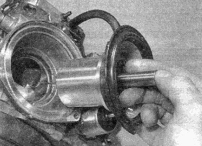
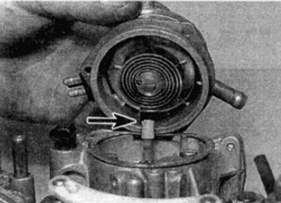
5. Remove the screws and lift up the carburetor damper cover with the piston (see fig. 8.5). Remove the gasket and destroy it - a new one must be installed during assembly.
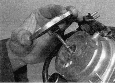
Pic. 8.5. Remove the screws and lift up the carburetor damper cover with the piston
6. Loosen and remove the screws, then lift the damper up out of the carburetor body. Note that the thermal delay valve is attached with one of these screws (see fig. 8.6, a, b).
Pic. 8.6, a. Loosen and remove the screws, then remove the damper from the carburetor body
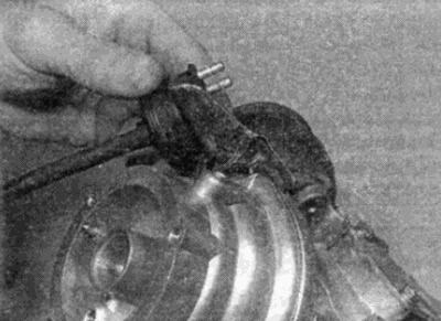
Pic. 8.6b. Note that the thermal delay valve is attached with one of the damper screws
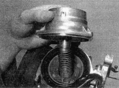
7. Remove the piston return spring, then remove the piston, diaphragm and jet needle from the carburetor - these parts are removed together as one unit (see fig. 8.7, a, b).
Pic. 8.7, a. Removing piston return spring...
Pic. 8.7b.... piston, diaphragm and jet needle from the carburetor body
8. Carefully check the piston diaphragm - hold it in front of a light source to illuminate the finger holes. If it is destroyed, punctured or perforated, the operation of the carburetor will be seriously impaired. Replace the diaphragm as follows: securely grip the piston and loosen the diaphragm fixing screws (see fig. 8.8).
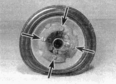
Pic. 8.8. Piston diaphragm fastening screws [shown by arrows)
9. Install the new diaphragm in place on the piston, making sure the folder on the underside of the diaphragm hub aligns with the notch on the top surface of the piston.
10. Install the washer on top of the diaphragm, then insert and tighten the mounting screws.
11. Install the piston assembly onto the carburetor body so that the tab on the outer rim of the diaphragm fits into the recess on the carburetor body (see fig. 8.11). When properly installed, the air holes on the piston base should face the engine.
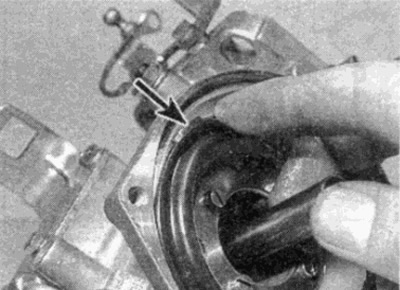
Pic. 8.11. Make sure the tab on the outer rim of the diaphragm (shown by arrow) matches the recess on the carburetor body
12. Install the piston return spring, then lower the damper into place, insert and tighten the screws. Remember that one of the screws secures the thermal delay valve. Note: To avoid mixing the diaphragm, do not rotate the damper when installing the damper on top of the piston.
13. Install damper cover and piston. Use a new gasket. Insert and tighten the fixing screws.
14. Unscrew the damper filler plug, then fill the shock absorber with the required oil in the required amount so that the level is just below the lower edge of the filler hole. Install and tighten the plug.
Jet needle
15. Remove the piston assembly from the carburetor as described in the previous section.
16. Loosen the grub screw on the side of the piston and remove the jet needle (see fig. 8.16).
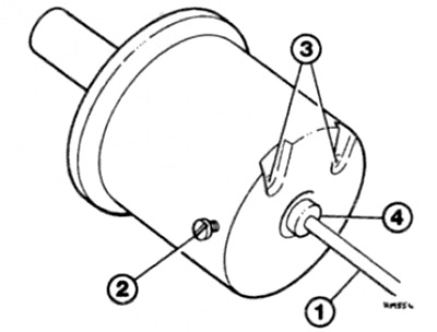
Pic. 8.16. Piston and jet needle
1 jet needle
2 countersunk screw
3 air ports
4 Plastic cuff
17. Carefully inspect the needle. If it is covered in dirt or tar, thoroughly clean it in carburetor cleaner. Be careful not to damage the needle. If significant wear is found on the side of the needle, it should be replaced, as this will negatively manifest itself during idling and partial throttle.
18. Insert the needle into the hole until the plastic collar is flush with the piston base. Tighten the grub screw.
19. Install the piston in the carburetor body. as described in the previous section.
Thermal delay valve
20. Check the operation of the thermal delay valve as follows - make sure the engine is cold, then turn on the ignition (do not start the engine). Disconnect the longer vacuum hose from the carburetor body and suck air through it. Initially, the valve should let air through, then 5-15 seconds after the ignition is turned on, the valve should close. If the valve passes air constantly or does not pass at all, it is probably defective and should be replaced.
21. Remove the short, curved hose from the fitting at the base of the thermo-delay valve; mark the nozzle in order to correctly install the hose in the future. Disconnect the plug on the valve block.
22. Turn away the screw and disconnect the valve from the carburetor.
23. Installation is carried out in the reverse order.
Trigger diaphragm
24. Disconnect all electrical wires and vacuum hoses from the air damper housing. Label each connector and hose for easy installation later.
25. Turn out screws and remove the case of a bimetallic spring from the case of an air damper. Do not remove cooling hoses. Remove the gasket.
26. Disconnect the connecting rod from the ball socket on the choke lever.
27. Remove the three screws and lift the choke body out of the carburetor body, remove the gasket and place the choke body on a workbench.
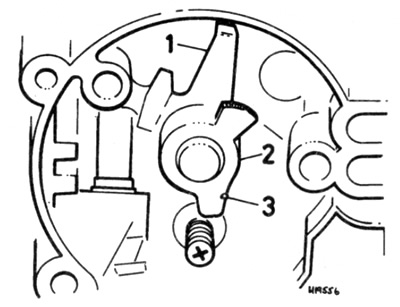
28. Remove retaining ring and remove choke lever, then dirt screen (see fig. 8.28).
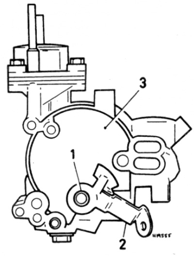
Pic. 8.28. Retaining ring (1), choke lever (2) and mud screen (3)
29. Turn out screws and remove a cover of a diaphragm of the starting device. Remove gasket (see fig. 8.29).
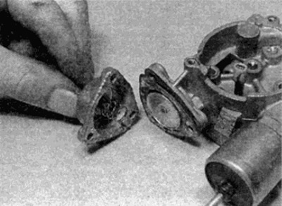
Pic. 8.29. Removing the Trigger Diaphragm Cover
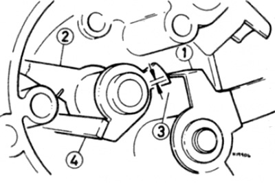
30. To separate the trigger diaphragm pusher, remove the retaining ring and move the control lever forward along with the high idle cam (see fig. 8.30).
Pic. 8.30. Auto choke lever (1), increased idle speed cam (2) and spring (3)
31. Remove the starter diaphragm and pusher from the air damper housing.
32. Carefully check the diaphragm. If damage or holes are found, the diaphragm must be replaced.
33. Assemble the air damper body as follows. Install the diaphragm and pushrod into the housing, then install the spring and cover using a new gasket. Tighten the screws securely.
34. Connect the choke control lever to the diaphragm pusher end of the starter and install the circlip.
35. To check the operation of the device, at this stage, install the choke lever without installing a dirt screen.
36. Push the trigger diaphragm pusher to the stop and push the control lever to the left so that it rests on the trigger pusher (those. to high idle position). The choke lever should rest against the center of the second highest step on the high idle cam. If adjustment is necessary, gently bend the control lever tongue.
37. After that, push the control lever to the left until it stops (those. to engine start position). The choke lever should now rest on the highest step on the high idle cam by at least 0.5 mm (see fig. 8.37) Again, gently bend the lever tab to adjust.
Pic. 8.37. Setting the choke lever to the cold start position
1 Choke lever
2 Control lever
3 Increased idle speed cam
4 Control lever tab. The arrows indicate the position of the choke lever at the highest step of the high idle cam at a distance of 0.5 mm
38. Finally, check that with the lever fully pressed to the right (those. normal idle position), the choke lever no longer rests on the stepped segment of the high idle cam.
39. After completing the choke adjustment, remove the choke lever, install the dirt screen and reinstall the choke lever. Secure the lever with the circlip.
40. Using a new gasket, install the choke body to the carburetor. After that, insert and screw the fastening screws.
41. Position the new gasket on the choke housing, then install the bimetal spring housing, making sure the tab of the spring is aligned with the choke control lever (see fig. 8.41). Set the assembly marks on both cases in line.
Pic. 8.41. Install the bimetal spring housing with the end of the spring (shown by arrow) behind the control lever
42. Install the tie rod into the spherical seat of the choke lever.
43. Using the notes made during disassembly, connect the electrical wires and vacuum hoses.