



Contents: Removal ↡ Installation ↡
Removal
Elements of the auxiliary drive belt tensioning mechanism with a shock absorber strut located under the tensioning mechanism
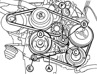
A – shock absorber strut; B – tension mechanism; C – tension mechanism bracket; D – bolt; E – bolt for fastening the lower part of the shock absorber strut; F – tension mechanism bolt
Elements of the auxiliary drive belt tensioning mechanism with a shock absorber strut located above the tensioning mechanism
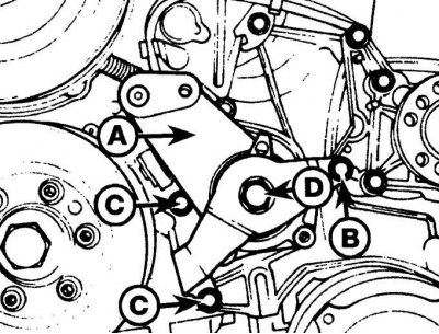
A – tensioning mechanism unit; B – bolt for fastening the tensioning mechanism unit to the power steering pump; C – bolts for fastening the tensioner bracket to the drive chain cover; D – central bolt
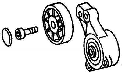
Auxiliary Drive Belt Tensioner Mechanism Parts Without Shock Absorber Strut
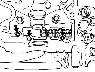
Location of bolts securing the upper part of the drive chain cover to the cylinder head
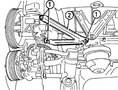
Location of mounting bolts (1) for air conditioning system mounting bracket and power steering pump (2)
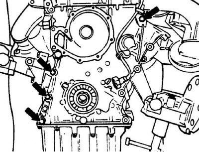
Location of bolts securing the drive chain cover to the engine cylinder block
1. Remove the radiator.
2. Remove the power steering pump.
3. Remove the front anti-roll bar.
4. Remove the oil pan.
5. Remove the auxiliary drive belt.
6. Unscrew the bolts and nuts and remove the auxiliary drive belt tensioner components (see fig. Elements of the auxiliary drive belt tensioning mechanism with a shock absorber strut located under the tensioning mechanism, Elements of the auxiliary drive belt tensioning mechanism with a shock absorber strut located above the tensioning mechanism, Parts of the auxiliary drive belt tensioning mechanism without a shock absorber strut).
7. On models with the shock absorber strut mounted under the tensioner, remove the bolt securing the lower end of the shock absorber strut and the bolt securing the tensioner bracket, and finally remove the center tensioner bolt. Remove the tensioner components from the engine.
8. On models with the shock absorber strut mounted above the accessory drive belt tensioner, remove the power steering pump pulley, then the tensioner pulley. Unscrew the shock absorber strut from the tensioner bracket. Unscrew the other end of the shock absorber strut from the alternator bracket. Secure the bolt securing the tensioner assembly to the power steering pump bracket from turning, and remove the nut from the bolt. Remove the two bolts securing the tensioner bracket to the drive chain cover. Remove the center tensioner bolt, then remove the tensioner assembly from the engine.
9. On models without a shock absorber strut, unscrew the bolt and remove the tensioner mechanism.
10. Remove the crankshaft pulley from the hub.
11. Unscrew the bolts and remove the water pump.
12. Remove the air filter housing.
13. Remove the ignition distributor.
14. If equipped, remove the rear self-leveling suspension pump mounting bolts and, without disconnecting the hydraulic hoses from the pump, move the pump to the side.
15. Remove the cylinder head cover.
16. Remove the three bolts securing the top of the timing chain cover to the cylinder head (see Fig. Location of bolts securing the upper part of the drive chain cover to the cylinder head).
17. If equipped, remove the three bolts and bracket that secures the air conditioning compressor and power steering pump (see Fig. Location of mounting bolts for the air conditioning system and power steering pump mounting bracket).
18. On models with air conditioning, loosen the air conditioning compressor mounting bolts and, without disconnecting the hoses from it, move the compressor to the side.
19. Remove the generator together with the bracket.
20. Remove the generator together with the bracket.
21. Unscrew the two bolts securing the oil pump oil pickup pipe to the main bearing cap and the nut securing the pipe to the bracket and remove the bracket.
22. Remove the remaining bolts securing the timing chain cover to the engine block. Mark the bolt locations as the bolts are different lengths. Remove the timing chain cover from the guide pins along with the oil pickup tube (see Fig. Location of bolts securing the drive chain cover to the engine cylinder block).
23. Remove the spacer sleeve from the front of the crankshaft.
Installation
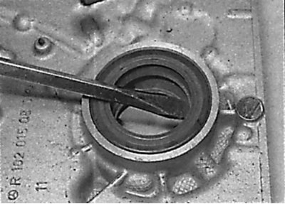
Removal the crankshaft seal ring from the timing chain cover
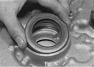
Installing a new crankshaft seal ring into the timing chain cover
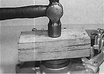
Installing the crankshaft seal ring using a wooden block
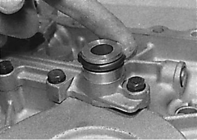
Checking the condition of the oil pickup tube sealing ring and applying a thin layer of engine oil to it
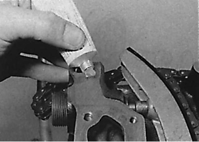
Applying a thin layer of sealant to the surface of the cylinder block that mated with the timing chain cover
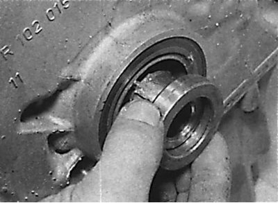
Installing a spacer sleeve on the front end of the crankshaft
1. Check the condition of the cylinder head gasket where it meets the timing chain cover.
2. Clean the mating surfaces of the engine block and timing chain cover from any remaining old gasket and sealant.
3. Using a screwdriver blade as a lever, remove the crankshaft sealing ring from the timing chain cover. Lubricate the outside of the new sealing ring with clean engine oil and install it in the timing chain cover (see Fig. Removing the crankshaft seal ring from the timing chain cover, Installing a new crankshaft seal ring into the timing chain cover, Installing the crankshaft seal ring using a wooden block).
4. Check the condition of the O-ring on the oil pickup tube at the rear of the oil pump (see fig. Checking the condition of the oil pickup tube sealing ring and applying a thin layer of engine oil to it). Lubricate the sealing ring with clean engine oil.
5. Install new gaskets or apply a thin layer of sealant to the surface of the cylinder block that meets the timing chain cover (see Fig. Applying a thin layer of sealant to the cylinder block surface mating with the timing chain cover).
6. Install the drive chain cover onto the guide pins.
7. Tighten the timing chain cover mounting bolts by hand.
8. Install the oil pickup pipe bracket and secure it with bolts and nut.
9. Install the spacer sleeve onto the front end of the crankshaft, being careful not to damage the front crankshaft seal ring (see Fig. Installing the spacer sleeve on the front end of the crankshaft).
10. Install the generator together with the bracket.
11. Install the air conditioning compressor and its bracket.
12. Install the air conditioning compressor and power steering pump mounting bracket.
13. Install the three bolts securing the timing chain cover to the cylinder head, but do not tighten them completely.
14. Tighten the timing chain cover mounting bolts evenly and in a diagonal sequence to the specified torque.
15. Tighten the three upper timing chain cover-to-cylinder head bolts to the specified torque.
16. If a new timing chain cover is installed, the position of the crankshaft angle sensor mounting bracket must be adjusted.
17. Connect the electrical connector to the crankshaft angle sensor.
18. Install the cylinder head cover.
19. Install the rear self-leveling suspension pump.
20. Install the ignition distributor.
21. Install the air filter.
22. Install the water pump.
23. Install the hub and crankshaft pulley onto the crankshaft.
24. Install the auxiliary drive belt tensioner components in the reverse order of removal.
Article was obtained from the portal MERCEDESMAN.ru
25. Install the oil pan.
26. Install the front anti-roll bar.
27. Install the power steering pump.
28. Install the radiator.