



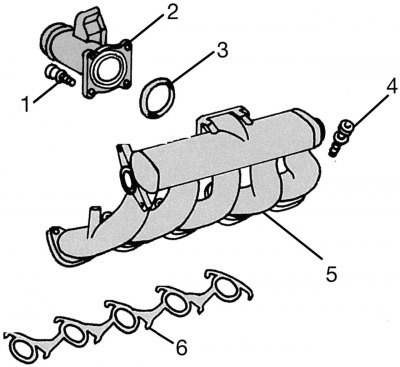
Figure 165. Mixing chamber and intake manifold (for 2.9L engine): 1 - bolt for fastening the chamber to the intake manifold; 2 - mixing chamber; 3 - sealing ring; 4 — bolt securing the intake manifold to the cylinder head; 5 - intake manifold; 6 - intake manifold gasket
The details of the mixing chamber are shown in the figure 165. The air intake hoses connected to it are not the same for both types of engines. In a turbocharged engine, a connecting element is installed between the mixing chamber and the air intake.
Removal and installation should be carried out in accordance with the drawing 165. The sealing ring on the inside of the chamber must always be replaced. Please note that in the places shown by the arrows it is securely held by the fastener. Tighten the bolts to a torque of 9 Nm.
[Original article is on the portal: MercedesMan.ru]