
Warning: If any part of the ABS system has been removed or replaced, check the operation of the system before operating the vehicle. This should be done in a workshop environment using special test equipment.
Models without Traction Control
Hydraulic modulator
Note: Please read the warning at the beginning before operation paragraph 2 about the dangers of hydraulic fluid.
Withdrawal
1. Disconnect the negative battery terminal.
2. Remove the master cylinder reservoir cap and add fluid to the level "MAX" (see chapter 1). Place a piece of polyethylene on top of the filler neck and close the cap securely. This will reduce brake fluid loss during subsequent operations. As a precaution, spread absorbent cloths under the hydraulic modulator.
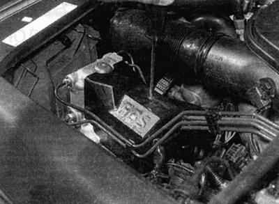
3. Wipe down the area around the hydraulic module tubing fittings, then record how the tubing is installed to properly reinstall (see fig. 18.3). Loosen the union nuts and carefully separate the tubes. Plug or tape the open ends and openings of the module to reduce brake fluid loss and prevent dirt from entering the system. Wash off any spilled liquid immediately with cold water.
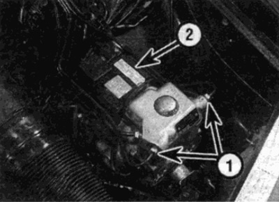
Pic. 18.3. Union of brake pipes of the ABS hydraulic module (1) and electrical connector (2)
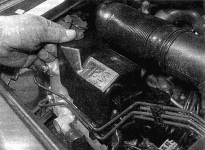
4. Loosen the mounting screw and remove the relay cover from the assembly to gain access to the wires. Disconnect the connector and remove it from the hydraulic module, then unscrew the mounting bolt and disconnect the ground bus.
5. Loosen and remove the mounting nuts, then pull the module out of the bracket. If necessary, unscrew the rubber bushings and remove them.
Note: Do not attempt to disassemble the hydraulic unit modulator block; not repairable.
Installation
6. Installation is carried out in the reverse order, taking into account the following points:
- A) Check the rubber bushings for wear or damage, replace if necessary.
- b) Install the brake pipes to their respective fittings and tighten the nuts to the correct torque.
- V) Make sure the wire is routed correctly and the connector is securely in place.
- G) When finished, before connecting the battery, bleed the brake system as described in paragraph 2.
Electronic control unit (ECU)
Withdrawal
7. ABS control unit (ZBU) located behind a plastic insulating cover that mounts on the back of the battery tray. Before removing, disconnect the negative terminal of the battery.
8. Pull back the rubber boot and remove the cover on the back of the battery. To improve access, unfasten the rubber sealing strip from the base of the windshield, then remove the retainer and unscrew the fastening screws and remove the part of the cover of the ventilation housing.
9. Release the connector latch and disconnect the connector, then slide the ECU out and remove it from the vehicle (see fig. 18.9).
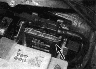
Pic. 18.9. Location of the ABS electronic control unit
Installation
10. Installation is carried out in the reverse order. Make sure the wire connector is connected securely.
Front wheel sensor
Note: New transducer mounting bolts are required for installation.
Withdrawal
11. Chock the rear wheels, apply the parking brake, then jack up the front of the vehicle and support it on jack stands (see "Lifting the vehicle and placing it on stands"). Remove the corresponding front wheel.
12. Make sure the ignition is off, then trace the wires back from the sensor to the connector. Unfasten the connector from the retainer and disconnect it from the main harness. Release the sensor wire from all holders and clamps, remembering how it is routed, so that it can be easily removed.
13. Loosen and unscrew the bolts securing the sensor to the steering knuckle and remove the sensor and wire from the car (see fig. 18.13). Check the sealing ring. If wear or damage is found, replace. Dispose of mounting bolts - new ones must be used for installation.
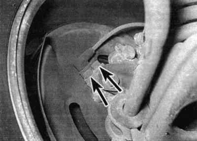
Pic. 18.13. Bolts of fastening of the gauge of a forward wheel (shown by arrows)
Installation
14. Before installation, make sure that the mating surfaces of the sensor and steering knuckle are clean and dry, then apply a thin layer of multi-purpose grease to them (Mercedes-Benz recommends Molycote Longterm 2).
15. Make sure the probe tip and magnetic rings are clean. Install the O-ring on the sensor.
16. Insert the sensor into the steering knuckle. Make sure that the sensor is correctly positioned, then install new mounting bolts and tighten them to the required torque.
17. Fasten the wires to all the holders and clamps provided for this in order to properly live them. Make sure the O-ring is in good condition, then connect the wires and fasten the connector into the retainer.
18. Install the wheel, then lower the vehicle to the ground and tighten the wheel bolts to the correct torque.
Rear wheel sensor
Withdrawal
Note: A new sensor mounting bolt will be required for installation.
19. Place wedges under the front wheels, then jack up the rear of the vehicle and support it on jack stands (see Lifting and jacking up the vehicle").
20. To get to the sensor connector, remove the rear seat as described in Chapter 11.
21. Make sure the ignition is off, then disconnect the sensor wires from the connector. Release the sensor wire from all holders and clamps, remembering how it is routed, so that it can be easily removed.
22. Working from below under the car, release the sensor wire from the holders on the bottom.
23. Turn away a bolt of fastening of the gauge and remove the gauge and a sealing ring from the main transfer (see fig. 18.23). Replace the O-ring if damaged or broken. Dispose of the mounting bolt as a new one must be used for installation.
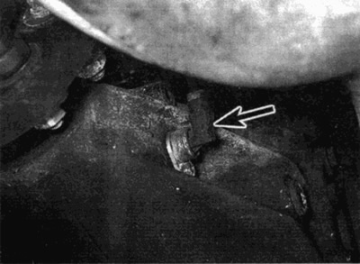
Pic. 18.23. The rear wheel sensor is mounted on the side of the final drive
Installation
24. Make sure the surfaces of the sensor and eye transmission are clean and dry and install the O-ring on the sensor.
25. Install the sensor in place, then install a new mounting bolt and tighten it to the required torque.
26. Route the wire back through the rubber grommet in the floor, then inside the passenger compartment and connect it to the main harness. Make sure that the wire is routed correctly and securely fasten it to the appropriate holders.
27. Install the rear seat and lower the vehicle to the ground.
Front magnetic rings
28. The front magnetic rings are fixed on the rear surface of the wheel hub. Check if the rings have crumbled and if all the teeth are in place. If replacement is necessary, replace the hub assembly as described in Chapter 10.
Rear magnetic ring
29. The rear magnetic ring is part of the final drive. With the sensor removed, check that the pi ring is not damaged. If teeth are broken or missing, replace. The replacement must be carried out at a Mercedes-Benz workshop.
Voltage protection relay
Withdrawal
30. The relay is located behind the electronic control unit (ECU). Make sure the ignition is off before removing.
31. Loosen the mounting screws (where installed), then disconnect the relay and remove it from the engine compartment.
Installation
32. When installing, make sure the relay and connector terminals are clean and dry.
ABS relay
Withdrawal
33. Loosen the fastening screw and remove the turnip cover from the top of the hydraulic module (see fig. 18.33, a, b).
Pic. 18.33, a. Loosen and remove the fixing screw...
Pic. 18.33 b....and remove the relay cover from the hydraulic module
34. Make sure the ignition is off and remove the appropriate relay from the control unit: the solenoid valve relay is smaller, and the return pump relay is the larger of the two (see fig. 18.34).
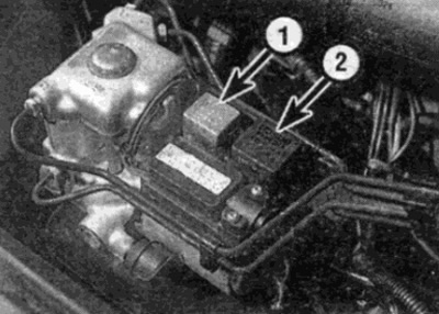
Pic. 18.34. Solenoid valve relay (1) and return pump relay (2)
Installation
35. Make sure the relays are securely seated in the sockets, then install the cover and tighten the mounting screws securely.
Models equipped with Traction Control
Hydraulic module
Note: Please read the warning at the beginning before operation paragraph 2 about the dangers of hydraulic fluid.
Withdrawal
36. Disconnect the negative battery terminal.
37. Loosen the mounting screws, then unfasten the covers and remove them from the top of the hydraulic module.
38. Connect a piece of hose to the hydraulic module air release valve (labeled SP1 and place the end of the hose in a container. Depressurize the hydraulic module by loosening the air release valve and allow the fluid to drain into a container.
39. Unfasten the latch and disconnect the wire connector from the hydraulic module.
40. Disconnect the hydraulic lines from the module as described in steps 2 and 3.
41. Unscrew the fastening nut and separate the ground bus from the module.
42. Turn away bolts of fastening and remove the hydraulic module upwards.
Note: Do not attempt to disassemble the hydraulic unit modulator block; not repairable.
Installation
43. Installation is carried out in the reverse order, taking into account the following points:
- A) Check the rubber bushings for wear or damage, replace if necessary.
- b) Install the brake pipes to their respective fittings and tighten the nuts to the correct torque.
- V) Make sure the wire is routed correctly and the connector is securely in place.
- G) When finished, bleed the air from the brake system (including hydraulic module), as described in paragraph 2.
Pressure pump
Withdrawal
44. Follow the steps described in pl. 36-38, inclusive.
45. To reduce the loss of brake fluid, clamp the hose connecting the injection pump to the main cylinder supply reservoir with a clamp.
46. Wipe area around pump hose and tubing fittings. Loosen the union nuts and carefully remove the tubes from the pump and disconnect the hydraulic hose. Plug or tape the ends of the tubing/hose and pump ports to minimize fluid loss and prevent dirt from entering the system. Rinse spilled liquid immediately with cold water.
47. Disconnect the electrical connector from the pump, release the pump from the support bracket and pull it out of the engine compartment.
Installation
48. Installation is carried out in the reverse order, taking into account the following points:
- A) Replace rubber mounts if damaged or broken.
- b) When finished, bleed the air from the brake system as described in paragraph 2, without forgetting the hydraulic module.
Pressure accumulator
Withdrawal
49. Follow the steps described in p.p. 36-38. inclusive.
50. Proceeding as described in steps 2 and 3, disconnect the pressure accumulator tubes from the base of the hydraulic unit.
51. Apply the parking brake, then jack part of the car up and place it on jack stands (see "Lifting the vehicle and placing it on stands"). Remove the left front wheel.
52. Turn away screws of fastening and remove a locker of a wheel arch of the left wing.
53. Remove the nuts securing the battery to the support bracket, then carefully remove the battery along with the hydraulic tubes.
Installation
54. Installation is carried out in the reverse order, taking into account the following points:
- A) When installing, make sure the hydraulic pipes are properly routed on top of the ring bracket.
- b) Tighten the nuts of the tube fittings to the required torque.
- V) When finished, bleed the brake system, including the hydraulic module, as described in paragraph 2.
Electronic control units (ECU)
55. Refer to paragraphs. 7-10, given that the hydraulic module ECU is the rear of the two units, and the throttle actuator ECU is located at the front.
Front wheel sensor
56. Refer to paragraphs 11 to 18.
Rear wheel sensor
Note: A new transducer mounting bolt and final drive support bolt nuts are required for installation. It is also necessary to replace the sensor O-ring.
Withdrawal
57. Place wedges under the rear wheels, apply the parking brake, then jack up the front of the vehicle and support it on jack stands (see "Lifting the vehicle and placing it on stands"). Remove the corresponding front wheel.
58. Turn away nuts of fastening and remove a gutter of wires of the gauge from a body of the car.
59. Position a wooden block jack under the final drive and raise the jack to support the weight of the assembly.
60. Turn away nuts of fastening and take out two bolts of back support of the main transfer.
61. Loosen and remove the nut and remove the final drive front support bolt.
62. Carefully lower the final drive until the propeller shaft touches the seat belt support rod or heat shield that is mounted across the body tunnel. Remove the washers and rubber bands from the front final drive support. Replace the rubber bands if they are damaged.
63. Loosen and remove the sensor mounting bolt, remove the sensor from the top of the final drive along with its O-ring. Replace O-ring.
64. Route the sensor wire back to the junction block and remove the cover. Turn the fastening ring and disconnect the wire connector from the block.
65. If both sensors are removed, mark between the sensor connectors and wires. Unfasten the cover from the reverse side of the connector, then release the sensor terminals and remove it from under the car.
Installation
66. Insert the sensor terminals into the connector, using the marks made during removal, and fasten the cover into place. Connect the connector to the block, securing it with the retaining ring. Install the cover.
67. Make sure that the surfaces of the sensor and final drive are clean and dry, then install a new o-ring on the sensor.
68. Establish the gauge on the main transfer, then establish a new bolt of fastening and tighten it with demanded effort.
69. Make sure that the rubber bands and washers of the upper and lower mounts are correctly positioned. Carefully lift the main gear into place.
70. Insert bolts of fastening of the main transfer and establish new nuts. Tighten the mounting bolts to the required torque (see chapter 8).
71. Make sure the sensor wire is properly routed, then install the wire tray and lower the vehicle to the ground.
Front magnetic rings
72 The front magnetic rings are attached to the rear surface of the wheel hub. Check if the rings have crumbled and if all the teeth are in place. If replacement is necessary, replace the hub assembly as described in Chapter 10.
Rear magnetic ring
73. The rear magnetic ring is an integral part of the final drive. With the sensor removed, check whether the ring is damaged. If teeth are found to be defective, replace. The replacement must be carried out at a Mercedes-Benz workshop.
Voltage protection relay
74. Refer to a a 30-32.
ASR system relay
75. Refer to paragraphs. 33-35.