



Removal
Note: Please read the warning at the beginning before you begin paragraph 2 about the dangers of hydraulic fluid.
1. Disconnect the negative battery terminal.
2. Disconnect the connector from the brake fluid level sensor.
3. Unscrew the master cylinder reservoir cap and remove the hydraulic fluid from the reservoir using a syringe. You can unscrew the brake system air release valve and smoothly press the brake pedal to force the fluid into a container through a tube connected to the valve (see paragraph 2).
(Original material on the website: «MERCEDESMAN.ru»)
Warning: Do not suck out the liquid by mouth as it is poisonous; use a syringe.
4. Where necessary, disconnect the hydraulic hoses from the side of the reservoir and plug the ends of the hoses to reduce fluid loss.
5. Carefully remove the fluid reserve tank from the master cylinder. Remove the reservoir seal and plug the cylinder holes to prevent dirt from getting in.
6. Wipe the area around the tube fittings on the side of the master cylinder, and place absorbent rags under the tube fittings to catch any spilled fluid. Note the location of the fittings, then loosen the fitting nuts and carefully pull the tubes out. Plug or cap the ends of the tubes and the openings in the cylinder to reduce fluid loss and prevent contamination of system components. Immediately flush any spilled hydraulic fluid with cold water.
7. Loosen and remove the two nuts and washers securing the master cylinder to the brake booster, then remove the assembly forward from the booster.
Note: Do not tilt the master cylinder until the pushrod is disconnected from the booster, otherwise the booster may be damaged.
Remove the O-ring from the rear of the master cylinder.
Repair
Note: Before disassembling the master cylinder, check with your Mercedes-Benz dealer for availability of spare parts, since there are two types of master cylinders installed on vehicles.
8. Remove all traces of dirt or dust from the cylinder body.
9. Remove the reserve tank seals from the master cylinder, noting the correct location of each seal (see fig. 10.9).
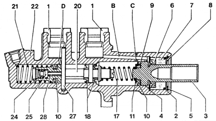
Fig. 10.9. Section of the master cylinder assembly - Teves model (other models are similar)
1 Support seals
2 Sealing ring
3 Main piston
4 Limiter washer
5 Retaining ring
6 Seal
7 Bushing
8 Washer
9 Seal
10 Seal
11 Spring cup
17 Spring
20 Secondary piston
21 Spring
22 Cylinder body
24 Valve spring
25 Valve seal
27 Secondary piston rod
28 Valve stem
In the Liquid Inlet Hole
With Compensation Hole
D Filling and compensation hole
10. Carefully clamp the cylinder in a vice with soft jaws, then use a drift to push the piston into the cylinder until the retaining rod can be removed from the reservoir nipple.
11. Press the piston back into the cylinder and remove the retaining ring from the master cylinder, along with its washer and sealing ring (where it is installed).
12. Remembering the correct location of each part, remove the main piston assembly and spring from the cylinder.
13. Tap the master cylinder body on a clean wooden surface and remove the secondary piston and spring from the cylinder, making a note of how the piston is installed.
14. Clean all parts thoroughly with ethyl or isopropyl alcohol or clean brake fluid. Never use gasoline or kerosene based solvents as they attack the rubber parts of the hydraulic system components. Dry the parts immediately with compressed air or a clean lint-free cloth. Use compressed air to blow out the fluid passages.
15. Check the condition of the parts and replace any that are worn or damaged. Check especially the cylinder bores and pistons; they need to be replaced (please note that the unit is changed as a whole) if they are scratched, worn or corroded. Likewise, check the condition of the pins and their bushings; both fingers must be intact, and (when thoroughly cleaned) fit tightly into the bushings. If there is any doubt about the condition of any part, replace it.
16. If the unit can be used further, purchase the appropriate repair kit from your Mercedes-Benz dealer. All rubber seals must be replaced; they cannot be reused.
17. Before installation, dip the piston and all seals in clean hydraulic fluid. Lubricate the surface of the cylinder bore with clean fluid.
18. Install the spring onto the secondary piston assembly and insert the piston into the master cylinder body, ensuring that it is seated correctly. Install the piston by rotating it from side to side, ensuring that the piston seals do not bind at the cylinder inlet.
19. Position the secondary piston so that the groove on the piston is correctly positioned in relation to the master cylinder body, then press the piston into place and secure it with the retaining ring.
20. Install the new master cylinder assembly as described in step 18.
21. Where provided, install a new O-ring onto the end of the master cylinder, then install the washer and snap ring. Ensure that the snap ring is correctly positioned in the groove of the master cylinder.
22. Install new master cylinder reserve reservoir seals onto the master cylinder pipes.
Installation
23. Remove all traces of dirt and dust from the master cylinder and brake booster. Install a new O-ring on the rear of the master cylinder body.
24. Install the master cylinder onto the brake booster, making sure the piston enters the master cylinder bore at the center. Install the cylinder mounting nuts and tighten them to the specified torque.
25. Wipe the brake pipe fittings, then install them on the master cylinder and tighten to the required torque.
26. Install the reserve tank on the cylinder and connect the hydraulic hoses where necessary.
27. Fill the master cylinder reservoir with new fluid and bleed the entire hydraulic system as described in paragraph 2. Before driving on the road, thoroughly check the operation of the brake system.