
Note: Please read the warning at the beginning before operation paragraph 4 about the dangers of asbestos dust.
Examination
Note: If at least one of the disks needs to be replaced. it is necessary to replace BOTH discs at the same time to guarantee the same braking torque on both wheels. Together with the discs, all four brake pads need to be replaced.
1. Apply the parking brake firmly, then jack up the front of the vehicle and place it on jack stands (see "Vehicle lifting and jacking up"). Remove the corresponding front wheel.
2. Slowly turn the brake disc so that you can view the entire disc from both sides. To improve the field of view of the inner surface of the disc, remove the brake pads. Small scratches are allowed on the surface under the pads, however, if there are significant scratches or cracks on the disc, it must be replaced.
3. It is considered acceptable to have a rusty step around the perimeter of the disk, which can be removed if desired. However, if the step is due to pad wear, check the thickness of the disc with a micrometer (see fig. 6.3). Measure at various points on the surface of the disc, on the inside and outside of the surface under the pads. If wear in at least one place exceeds the maximum allowable by technical data, the disc must be replaced.
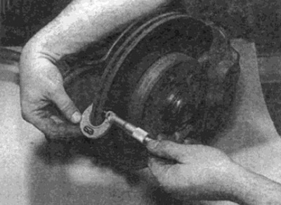
Pic. 6.3. Measuring disc thickness with a micrometer
4. Check the axial runout of the brake disc (see fig. 6.4). However, first, rule out end play in the hub bearing as a possible source of the problem (see chapter 10).
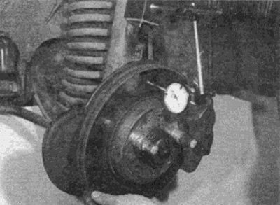
Pic. 6.4. Checking disc runout with a dial micrometer (rear disc shown - same procedure for front disc)
5. To check disc runout, place large flat washers under the heads of the two wheel bolts and thread them into the hub through the disc. Position the bolts diagonally so that the blade is level, then tighten the bolts. You can use a pointer indicator mounted on some fixed support, or use flat feelers to measure the gap (at some points on the entire surface of the disk) between the disc and a fixed surface such as a caliper mounting bracket. If the values obtained are outside the limits specified in the technical data, then the disc should be replaced.
6. Check for cracks in the disc, especially around the bolt holes. If cracks are found, as well as wear or other damage, the disc should be replaced.
Replacement
Note: New caliper mounting bolts and disc mounting screws are required for installation.
7. Remove the two bolts holding the brake caliper bracket to the steering knuckle, then slide the caliper off the disc. Tie the caliper to the front suspension spring so you don't stretch the hydraulic hoses or wires from the caliper. Dispose of bolts, new ones must be used for installation (see fig. 6.7).
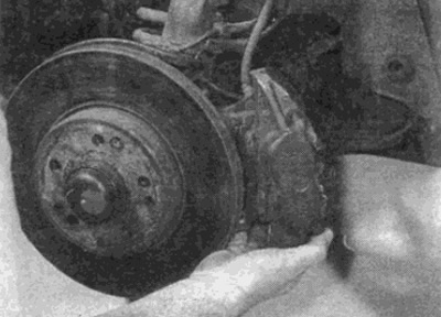
Pic. 6.7. Loosen the bolts and remove the caliper from the steering knuckle...
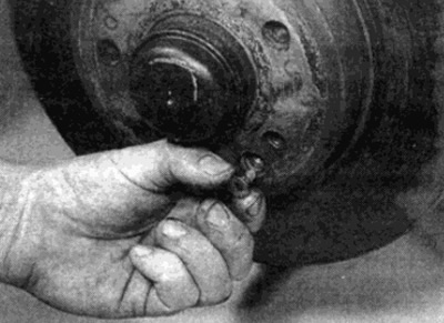
8. Loosen and remove the screws securing the brake disc to the hub (see fig. 6.8). Dispose of the screws as new ones must be used for installation.
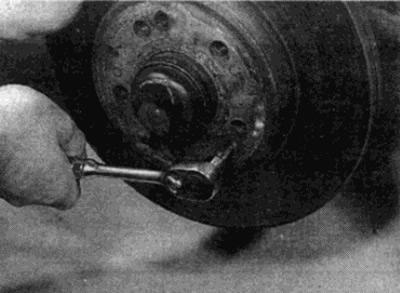
Pic. 6.8....then unscrew the fastening screws and remove the brake disc
9. Remove a disk from a nave, remembering the correct arrangement of its adjusting fingers. If it sits tight, lightly tap on the back with a wooden mallet.
Installation
10. Before installation, remove all traces of the old fixing compound from the threads of the caliper mounting bolt hole by passing through the holes with a tap of the appropriate size. Similarly, clean the threads of the hub holes for the disc mounting screws.
Advice. If you do not have the required tap, go through the thread using an old slotted bolt on the thread.
11. Check that the mating surfaces of the disc and hub are clean and flat and that the dowel pins are in place. If a new disc is being installed, use a suitable solvent to remove the protective layer from the disc. Apply a thin coat of high temperature grease to the mating surfaces of the hub, but ensure that the disc surface is not contaminated.
12. Install the disc on the hub, properly positioning it on the locating pins. Install a new mounting screw and tighten it to the required torque (see fig. 6.12).
Pic. 6.12. When installing, secure the drive with a new mounting screw
13. Move the footport on top of the platter, making sure the pads go on each side of the platter.
14. Establish new bolts of fastening of an arm of a support and tighten them with the demanded moment.
15. Install the wheels, then lower the vehicle to the ground and tighten the wheel bolts to specification. Depress the brake pedal several times until the pads press against the brake disc and normal pedal pressure is restored. Thoroughly check the operation of the brakes before leaving on the road.