
Note: New rear driveline nuts, axle shaft pivot bolts, and final drive support bolt nuts are required for installation.
Removing
1. Place wedges under the front wheels. Raise the rear of the car and place it on stands (see "Vehicle lifting and jacking up"). Remove both rear wheels.
2. On models with ABS, do the following:
- A) Drain the oil from the final drive as described in Chapter 1.
- b) Talk to Chapter 9 and remove the wheel speed sensor from the final drive housing.
3. As described in Chapter 4D, remove the nuts and lower the exhaust heat shields.
4. Using an open-end wrench on "41" Loosen the driveline coupling nut two turns. located just behind the middle support bearing. Use the second key. to hold the driveshaft stationary while loosening the nut.
5. Turn away two screws of fastening of the average basic bearing of cardan transfer to the body bottom.
6. Turn away three nuts and turn away bolts of fastening of the back elastic coupling of cardan transfer to a differential gear wheel flange.
7. Move the driveline forward as far as possible to disengage the pinion flange centering sleeve. Move the disconnected propeller shaft to the side and support it by tying it to the parking brake cable with a rope.
8. Turn away bolts of fastening of both hinges of equal angular speeds on differential leading flanges. Remove bolts and fixing plates.
9. Push the shafts outward to separate them from the drive flanges. Using a piece of string, tie the shafts to the rear camber strut.
10. Position a jack under the final drive housing and support the assembly.
11. Unscrew the bolts securing the rear of the final drive housing to the subframe and remove the bolts together with the fixing plates (see fig. 3.11).
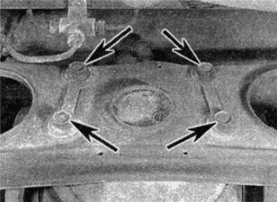
Pic. 3.11. Rear bolts securing the final drive housing to the subframe (shown by arrows)
12. Turn away a nut and remove a bolt of fastening of the case to a stretcher in front (see fig. 3.12).
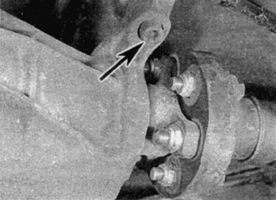
Pic. 3.12. Bolt of fastening of the case of the main transfer to a subframe (shown by arrow)
13. Lower a jack and pull out the case of the main transfer from under the car.
Installation
14. To install the assembly, position it in the center of the subframe and hand-tighten the front mounting bolt and nut.
15. Install the four rear mounting bolts and fixing plates and tighten them to the required torque. After that, also tighten the front nut and bolt to the required torque.
16. Place the propeller shaft on top of the pinion flange centering sleeve and secure the flexible coupling to the pinion flange with three nuts and bolts.
17. Install the two center support bearing mounting bolts, but hand-tighten at this stage.
18. With the propeller shaft in place, tighten the coupling nut, then fully tighten the middle bearing mounting bolts to the required torque.
19. Install exhaust heat shields.
20. Lubricate the threads of the inner CV joint bolts to the differential drive flange with light oil, then install the bolts with fixing plates and tighten them to the required torque.
21. On ABS equipped models, install the speed sensor and secure it with the mounting bolt after removing any metal particles that may collect on the sensor's magnetic probe.
22. Turn away a stopper of a jellied/control opening and fill or add oil in the final transfer to the lower edge of a control aperture. Install the plug and tighten it securely.
23. Lower the car to the ground.