
Cars BMW Cars Volkswagen Cars Chevrolet Cars Land Rover Cars Lada Cars Honda Cars Peugeot
English Русский
Български
Беларускі
Український
Српски
Hrvatski
Română
Polski
Slovenský
Magyar
Bookmark News and articles Sitemap Feedback Site search
MercedesMan.ru


A-Class C-Class E-Class G-Class M-Class S-Class Others
190 (W201) (1982-1993) W202 (1993-2000) W203 (2000-2007)
  • Main
  • C-Class
  • W201 (1982-1993)
  • Transmission
  • Cardan shaft and axle shafts
  • Protective half shaft covers — replacement

Protective half shaft covers — replacement (Mercedes-Benz C-Class W201)

0
1. Remove the axle shafts as described in paragraph 5.

2. Clean the axle shaft and secure it in a vice.

3. Use a lever to pry the sealing cap off the end of the inner CV joint (see fig. 6.3).
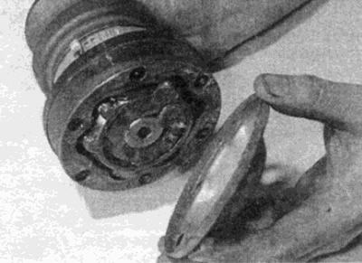
Fig. 6.3. Remove the sealing cover from the end of the inner CV joint

Fig. 6.3. Remove the sealing cover from the end of the inner CV joint


4. Cut/loosen the two inner CV joint boot clamps and move the boot along the axle shaft (see fig. 6.4).
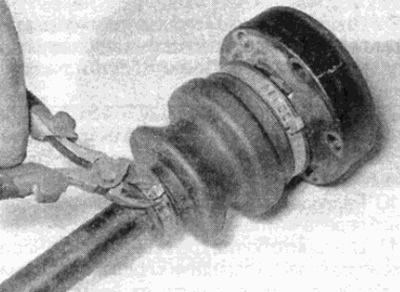
Fig. 6.4. Cut the clamps and separate the inner cover from the hinge

Fig. 6.4. Cut the clamps and separate the inner cover from the hinge


5. Wipe off excess grease and remove the inner joint snap ring from the axle shaft (see fig. 6.5).
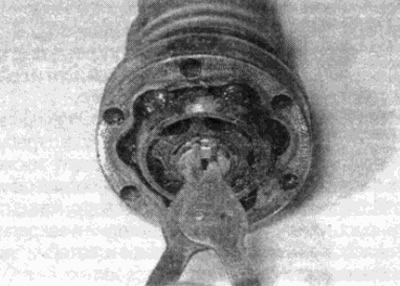
Fig. 6.5. Remove the retaining ring and knock out/pull out the inner joint from the axle shaft

Fig. 6.5. Remove the retaining ring and knock out/pull out the inner joint from the axle shaft


6. Support the inner member securely and tap out the axle shaft using a hammer and appropriate drift. If the joint is tight, use a puller to pull the joint out. Do not disassemble the inner joint.


7. Once the joint is removed, slide the boot off the end of the axle shaft.

8. Loosen the outer joint boot clamp, then move the boot along the axle shaft and remove it.

9. Clean the CV joints thoroughly in kerosene or a suitable solvent and dry thoroughly. Inspect the CV joint as follows.

10. Move the internal spline assembly from side to side to inspect each ball in turn at the top of the race. Check for cracks, flattening, or pitting on the balls.

11. Check the ball races on the inner and outer joints. If the races are wide, the balls will not fit tightly. At the same time, check for wear or cracks in the separators. If necessary, the mudguards can be removed from each joint and replaced. When installing, make sure the mating surfaces of the joint and cover are clean and dry, then apply a layer of sealant to the surface of the cover to prevent leaks.

12. If any of the CV joint components are found to be worn or damaged during inspection, the component should be replaced. Inner CV joints can be purchased separately, but if the outer CV joint is worn, the CV joint assembly and axle shaft will have to be replaced. If the joints are in satisfactory condition, purchase a new repair kit, which consists of boots, clamps, an inner CV joint retaining ring, and special grease.

13. Cover the splined end of the axle shaft with tape.

14. Place the new outer boot onto the end of the axle shaft.

15. Put special grease into the outer joint. Turn the joint to distribute the grease along the bearing tracks and put the rest into the rubber boot (see fig. 6.15).
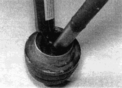


Fig. 6.15. Apply the grease supplied in the repair kit to the outer joint of the axle shaft

Fig. 6.15. Apply the grease supplied in the repair kit to the outer joint of the axle shaft


16. Spread the boot over the joint and check that the boot edges are correctly positioned on both axle shaft and CV joint connections. Lift the outer edge of the boot to release excess air from the boot (see Fig. 6.16, a, b).
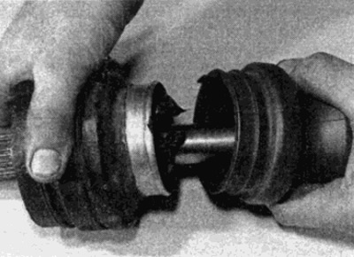
Fig. 6.16, a. Slide the new cover into place...
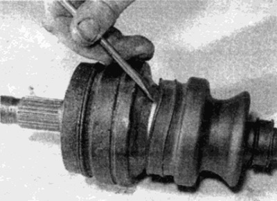
Fig. 6.16, a. Slide the new cover into place...


Fig. 6.16, b....then lift the outer sealing edge of the boot to release excess air from the boot

Fig. 6.16, b....then lift the outer sealing edge of the boot to release excess air from the boot


17. Install a large metal clamp on the cover. Tighten the clamp as much as possible and hook the hook into one of the slots. Select the free play of the clamp by squeezing the raised part of the clamp with special pliers; if you don't have special pliers, carefully squeeze the clamp using pliers, taking precautions not to damage the clamp. Secure the small clamp using a similar method (see Fig. 6.17, a, b).
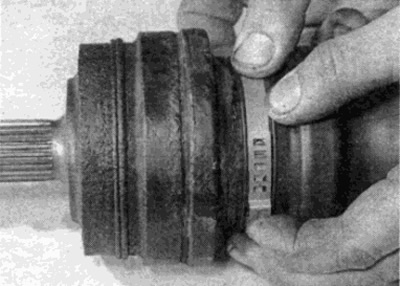


Fig. 6.17, a. Tighten the clamp tightly around the cover...
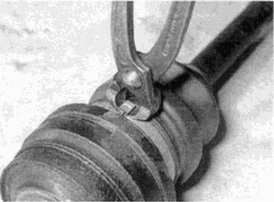
Fig. 6.17, a. Tighten the clamp tightly around the cover...


Fig. 6.17, b....and take up all the slack by squeezing the raised part of the clamp

Fig. 6.17, b....and take up all the slack by squeezing the raised part of the clamp


18. Place the new inner joint boot on the axle shaft (see fig. 6.18).
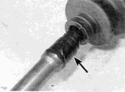
Fig. 6.18. Put on the new inner hinge cover, then remove the protective tape (shown by arrow)...

Fig. 6.18. Put on the new inner hinge cover, then remove the protective tape (shown by arrow)...


19. Remove the adhesive tape from the axle shaft splines and install the inner CV joint. Press the joint all the way onto the axle shaft and secure it with a new snap ring (see fig. 6.19).
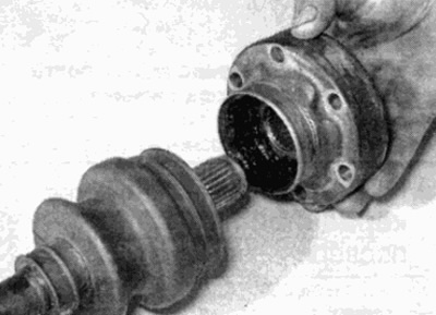


Fig. 6.19. ...and install the inner hinge assembly

Fig. 6.19. ...and install the inner hinge assembly


20. Put the grease supplied in the repair kit into the inner joint and put the rest into the boot (see fig. 2.20).
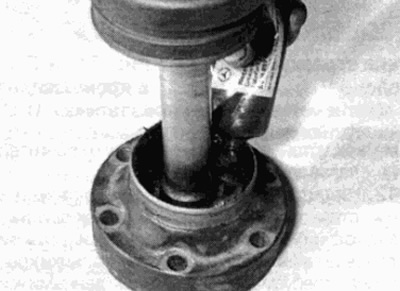
Fig. 6.20. Apply special grease to the inner joint

Fig. 6.20. Apply special grease to the inner joint


21. Spread the boot over the joint and check that the boot edges are correctly positioned on both axle shaft and CV joint connections. Lift the outer edge of the boot to release excess air from the boot. Secure the boot with clamps (see item 17).

22. Make sure the mating surfaces of the hinge and cover are clean and dry and apply a layer of sealant to the inner edge of the cover and press the cover until it stops on the inner hinge (see fig. 6.22).
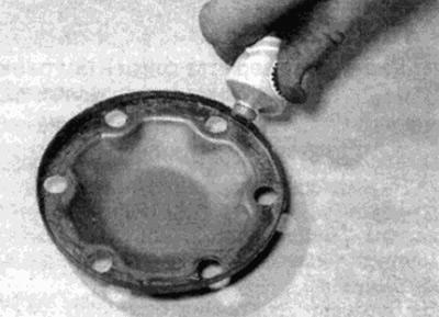
Fig. 6.22. Ensure that the sealing mating surface of the cover is clean and dry and apply a coat of…

Fig. 6.22. Ensure that the sealing mating surface of the cover is clean and dry and apply a coat of sealant before installing it onto the inner hinge


23. Check that both constant velocity joints can move freely, then install the axle shafts as described in paragraph 5.
This article is available at: russian, bulgarian, belarusian, ukrainian, serbian, croatian, romanian, polish, slovak, hungarian
The article has been verified: Lukyanov Nikita Ilyich
Share with friends:
◀ Previous
C-Class 190 (W201) / Cardan shaft and axle shafts
Next ▶

Half shafts — removal and installation
Main gear oil seals — replacement
Main gear — removal and installation
Main gear — draining and filling with oil
Basic information
Cardan transmission — removal and installation
Rubber couplings of the cardan transmission — inspection and replacement
Cardan shaft support bearing — inspection and replacement
Universal joint of the cardan transmission — inspection and replacement
More similar articles for repairing other models

☛ Protective bumper pads — removal and installation Mercedes W168 (1997-2004)
☛ Replacement of protective covers of CV joints of the drive shaft Mercedes W124 (1984-1995)
☛ Checking the condition of the drive shaft boots Mercedes W463 (1999-2019)
☛ Checking the condition of the drive shaft boots Mercedes W163 (1997-2005)
☛ Checking the condition of the protective covers of the drive shafts Mercedes W140 (1991-1998)
☛ Checking the steering gear protective covers Mercedes Sprinter (1995-2000, diesel)
Link in different formats to this article
Comments and feedback from visitors
No comments yet


How much will 41 + 15 ?


W203 (2000-2007) 
  • General information
  • Introduction to guide
  • User manual
  • Maintenance
  • Power unit
  • Gasoline engines
  • Diesel engines
  • Cooling system
  • Ventilation and heating
  • Supply system
  • Injection system (gasoline)
  • Injection system (diesel)
  • Exhaust system
  • Ignition and control system
  • Charge and launch systems
  • Transmission
  • Mechanical gearbox
  • Automatic gearbox
  • Clutch and drive shafts
  • Differential
  • Chassis
  • Brake system
  • Car suspension
  • Steering
  • Body
  • Exterior (external elements)
  • Interior (internal elements)
  • Electrical equipment
  • Equipment and devices
  • Lighting system
  • Electrical diagrams (2000)
  • Electrical diagrams (since 2001)
W202 (1993-2000) 
  • General information
  • User manual
  • Driving a car
  • Car care
  • Maintenance
  • Power unit
  • Gasoline engines
  • Diesel engines
  • Lubrication system
  • Cooling system
  • Heating and ventilation
  • Ignition system
  • Fuel system
  • Injection system (gasoline)
  • Injection system (diesel)
  • Exhaust system
  • Transmission
  • Clutch
  • Car gearbox
  • Chassis
  • Suspension, wheels and tires
  • Steering
  • Brake system
  • Body
  • Exterior (external elements)
  • Interior (internal elements)
  • Doors and windows
  • Electrical equipment
  • Equipment and devices
  • Power devices
  • Lighting system
  • Electrical circuits
190 (W201) (1982-1993) 
  • General information
  • Introduction to the guide
  • Operation and care
  • Maintenance (gasoline)
  • Maintenance (diesel)
  • Troubleshooting
  • Power unit
  • Petrol engine I4
  • Petrol engine V6
  • Diesel engines
  • Engine overhaul
  • Cooling and heating
  • Power system (carburetor)
  • Injection system (gasoline)
  • Injection system (diesel)
  • Exhaust system
  • Charge and start system
  • Ignition system (I4)
  • Ignition system (V6)
  • Diesel heating system
  • Transmission
  • Clutch
  • Mechanical gearbox
  • Automatic gearbox
  • Cardan shaft and axle shafts
  • Chassis
  • Brake system
  • Car suspension
  • Steering
  • Body
  • Exterior (external elements)
  • Interior (internal elements)
  • Doors, locks and windows
  • Electrical equipment
  • Equipment and devices
  • Electrical circuits
 
MercedesMan.ru © 2017–2026 · Mobile version · Read about Mercedes · Sitemap: EN BG BY UA RS HR RO PL SK HU · Feedback · Site search · Bookmark A-Class (W168) · C-Class (W201) · C-Class (W202) · C-Class (W203) · E-Class (W123) · E-Class (W124) · E-Class (W210) · G-Class (W463) · M-Class (W163) · S-Class (W116, petrol) · S-Class (W126, petrol) · S-Class (W140) · S-Class (W220) · Sprinter · Vito 1 · Vito 2 · Vario 814D ·
 
We only use cookies without which some of the site's features may not be available.