
Examination
1. Apply the parking brake, then raise the front of the vehicle and support it on jack stands (see "Vehicle lifting and jacking up").
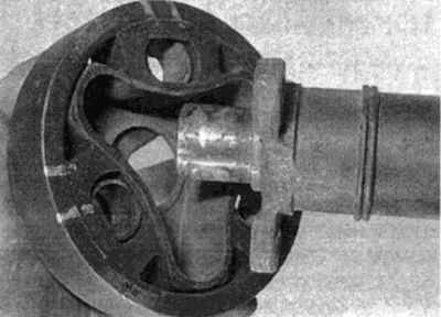
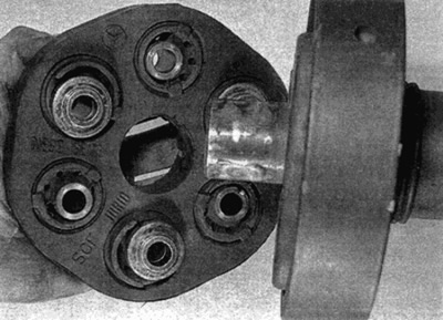
2. Carefully check the rubber couplings that connect the driveline to the gearbox and final drive. Look for damage such as cracks, delamination or general breakage. If necessary, replace the clutch as follows.
Replacement
Note: New driveline clutch nuts will be required.
3. Remove the driveline as described in paragraph 7.
Front clutch
4. Apply alignment marks between coupling and vibration damper (where it is installed) and cardan shaft.
5. Turn away nuts of fastening, then take bolts and remove the coupling from cardan transfer. Check the condition of the vibration damper, If wear or damage is found, replace.
6. Position the vibration damper (where it is installed) according to the marks made before removal. On models where the centers of the bolt holes are offset by 40 mm from the center of the shaft (bolt hole center diameter is 80 mm) the absorber should be positioned in this way. so that the molded pointer points as shown (see fig. 8.6, a, b).
Pic. 8.6. A. Vibration damper installation
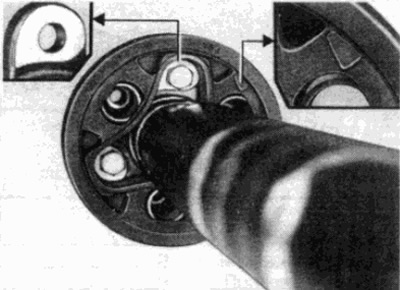
Pic. 8.6b. On models where the centers of the bolt holes are offset 40 mm from the center of the shaft, the vibration damper should be installed with the pointer oriented as in fig.
7. On models where the centers of the bolt holes are 45 mm or more from the center of the shaft (diameter 90 mm or more), position the absorber so that the arrow points towards the rising boss on the flange (see fig. 8.7, a, b).
Pic. 8.7, a. On models where the hole centers are 45mm or more off center, position the vibration damper so that the arrow points towards the raised boss on the flange (shown by arrow) - release models up to 12/89
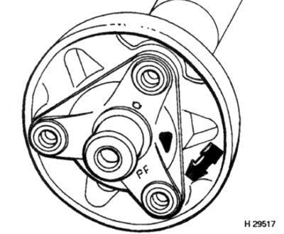
Pic. 8.7b. Vibration Damper Alignment Arrow Location - Models Released After 01/90
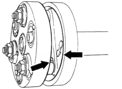
8. Install the new coupling onto the shaft, making sure that the labeled side "dese seite zur gelenkwelle" turned towards the cardan shaft (where needed) (see fig. 8.8). Insert the mounting bolts, then install new mounting nuts and tighten them to the required torque.
Pic. 8.8. Install the rubber sleeve, making sure the printed side is facing the damper/propeller shaft
9. Install the driveline as described in paragraph 7.
Rear clutch
10. Turn away nuts of fastening, then pull out bolts and remove the coupling from cardan transfer.
11. Install a new coupling, then install the mounting bolts and new nuts, tightening them to the required torque.
12. Install the driveline as described in paragraph 7.