



Contents: Petrol models ↡ Diesel models ↡
Note: Each section of the exhaust system can be removed individually if necessary.
Petrol models
M111
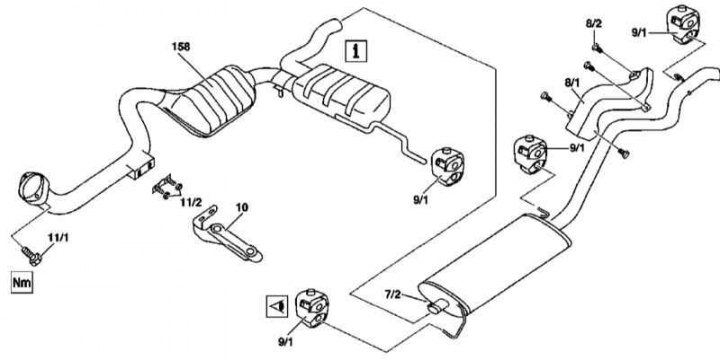
Exhaust system component installation details for 163.136 models (111 series engine)
7/2 - Rear section mounting clamp; 8/1 - Heat shield; 8/2 - Bolts; 9/1 - Rubber suspension; 10 - Exhaust system suspension bracket on transmission housing; 11/1 - Bolts; 11/2 - Nuts; 158 - Catalytic converter
Full article available on the resource (MercedesMan.ru)
1. Installation details of exhaust system components on 163.136 models (111 series engine) are shown in the illustration, to which all references found in the text refer.
2. Remove the heat shield (8/1).
3. Loosen the clamp (7/2) securing the rear section of the exhaust system - the clamp is welded to the section's connecting pipe.
4. Remove the rear section of the system from the rubber suspensions (9/1), assess the condition of the latter, and replace them if necessary.
5. Separate the front section of the exhaust system from the rear.
6. Remove the rear section and visually assess the condition of the heat shields on the underbody of the vehicle.
7. Support the transmission and remove the rear powertrain mount (see Chapter Engine).
8. Loosen the nuts (11/2) on the support bracket (10) - the nuts must be replaced without fail.
9. Remove the front section of the exhaust system from the rubber mounts (9/1), replace any faulty mounts.
10. Unscrew the bolts (11/1) of the flange connecting the inlet pipe to the exhaust manifold; if necessary, replace the manifold nuts.
11. Remove the front section assembly with the catalytic converter (158) and visually assess the condition of the heat shields on the underbody of the vehicle.
12. Installation is carried out in reverse order.
Attention! Disposal of failed catalytic converters must be carried out in compliance with legal regulations!
M112/113 (except ML 55 AMG)
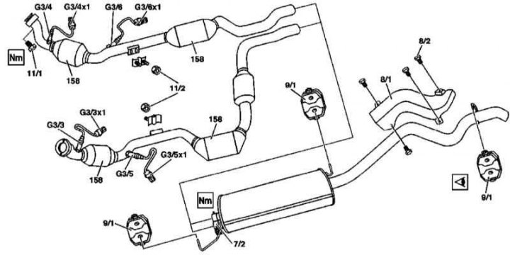
Installation details of exhaust system components on models with 112 and 113 series engines, except ML 55 AMG
7/2 - Rear section mounting clamps; 8/1 - Heat shield; 8/2 - Bolts; 9/1 - Rubber suspension; 11/1 - Bolts; 11/2 - Nuts; 158 - Catalytic converter; G3/3 - Left pre-catalytic lambda probe; G3/3x1 - Contact connector for the left pre-catalytic lambda probe wiring; G3/4 - Right pre-catalytic lambda probe; G3/4x1 - Contact connector for the wiring of the right pre-catalytic lambda probe; G3/5 - Left post-catalytic lambda probe; G3/5x1 - Contact connector for left post-catalytic lambda probe wiring; G3/6 - Right post-catalytic lambda probe; G3/6x1 - Contact connector for the wiring of the right post-catalytic lambda probe
1. Installation details of exhaust system components on models equipped with 112 and 113 series engines (except ML 55 AMG), are shown in the illustration, to which all references found in the text refer.
2. Jack up the front of the car and place it on supports.
3. Remove the front suspension torsion springs (see Chapter Suspension and steering).
4. Disconnect the electrical wiring from the sensors.
5. Remove the heat shield (8/1).
6. Loosen the clamps (7/2) securing the rear section of the exhaust system.
7. Remove the rear section from the hangers (9/1) - replace any faulty hangers.
8. Separate the rear section from the front sections and remove it from under the vehicle.
9. Visually assess the condition of the underbody heat shields and replace any defective components.
10. Loosen the nuts (11/2) securing the front sections of the exhaust system - the nuts must be replaced without fail.
11. Unscrew the bolts (11/1) of the flanges connecting the inlet pipes to the exhaust manifolds; if necessary, replace the manifold nuts.
12. Remove the front sections together with the catalytic converters.
13. Installation is carried out in reverse order.
Attention! Disposal of failed catalytic converters must be carried out in compliance with legal regulations!
ML 55 AMG models
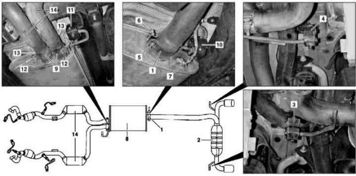
Installation details of exhaust system components on ML 55 AMG models
6 - Nut; 12 - Bolt; 13 - Nut; 14 - Front sections of the exhaust system
1. The installation details of the exhaust system components on the ML 55 AMG models are shown in the illustration to which all references in the text refer.
2. Loosen the clamp (1) securing the rear section of the exhaust system - the clamp nut must be replaced without fail.
3. Remove the rear section together with the muffler (2), assess the condition of the rubber suspensions (3 and 4), replace the faulty components.
4. Disconnect the ground bus (7) from the main muffler (8).
5. Loosen the welded clamps (9) of the muffler mount (8) - the clamp nuts (13) must be replaced without fail.
6. Separate the muffler from the front sections of the exhaust system and remove it from under the vehicle - replace damaged hangers (10 and 11).
7. Separate from the exhaust manifolds and remove the front sections of the exhaust system.
8. Installation is carried out in reverse order.
Attention! Disposal of failed catalytic converters must be carried out in compliance with legal regulations!
Diesel models
M612
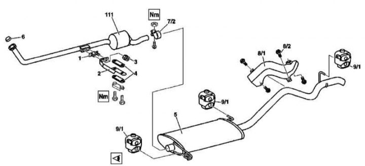
Exhaust system component installation details for 163.113 models (612 series engine)
1 - Threaded plate; 2 - Exhaust system suspension bracket on transmission housing; 3 - Self-locking nut; 4 - Rubber suspension; 5 - Rear section with muffler; 6 - Sealing cone; 7/2 - Fastening clamp; 8/1 - Heat shield; 8/2 - Bolts; 9/1 - Rubber suspension; 111 - Three-way catalytic converter (TWC)
1. Installation details of exhaust system components on 163.113 models (612 series engine) are shown in the illustration, to which all references found in the text refer.
2. Remove the lower section of sound insulation.
3. Remove the heat shield (8/1).
4. Loosen the mounting clamp (7/2) welded to the connecting pipe, separate the rear section (5) of the exhaust system from the front and remove it from under the vehicle.
5. Visually assess the condition of the bottom heat shields and replace any faulty elements.
6. Release the spring connection securing the primary catalytic converter to the three-function converter (TWC - 111) - the sealing cone (6) must be replaced during assembly.
7. Loosen the nuts (3) of the support bracket (2) - the nuts must be replaced without fail.
8. Support the front section of the exhaust system with a jack and unbolt the support bracket (2) from the transmission housing.
9. Remove the front section of the exhaust system complete with TWC (111) from under the vehicle and visually assess the condition of the underbody heat shields - replace any defective components.
10. Installation is carried out in reverse order.
Attention! Disposal of failed catalytic converters must be carried out in compliance with legal regulations!
M628
No information provided.
Optional AMG package tailpipe - all models except ML 55 AMG
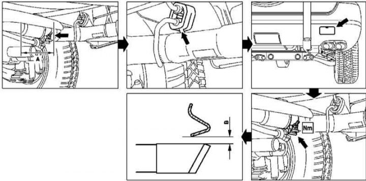
Installation details of the optional AMG package tailpipe - all models except ML 55 AMG
A = 140 mm
B = Not less than 15 mm
1. The installation details of the optional AMG package tailpipe for all models except the ML 55 AMG are shown in the illustration to which all references in the text refer - proceed in the order shown in the illustration.
2. Remove the exhaust system (see above), replace any faulty components.
3. Cut off the standard exhaust pipe at a distance of A = 140 mm from the center of the weld, in the area where the diameter of the branch pipe changes (arrow).
4. Cut the pins of the hanging rings (arrows).
5. After gluing self-adhesive foil (arrow) to the rear bumper trim in the area where the decorative cover of the towing eye is located, make a cutout in the lower skirt along its contour - the exhaust pipe should fit freely in the cutout.
6. Sand the edges of the cutout and varnish them.
7. Fasten the purchased AMG package tip to the rear section of the exhaust system - the overlap of the fastening clamp must be at least 50 mm.
8. Install the exhaust system and ensure that the exhaust tip is parallel to the underbody at least 15 mm below the skirt edge.