
Pedal Assembly Details
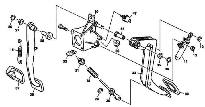
The design of the pedal assembly
10 - Holder; 11 - GTZ; 12 - Retaining ring; 13 - Nut; 15 - Return spring; 18 - Auxiliary spring; 25 - Foot brake pedal; 26 - Retaining ring; 27 - Washer; 28 - Bushing; 29 - Retaining ring; 30 - Pusher rod; 31 - Spring plate; 32 - Retainer; 33 - Clutch pedal; 34 - Retaining ring; 35 - Washer; 37 - Brake pedal pad; 38 - Clutch pedal pad; 44 - Sleeve
Note. See also Section Removal and installation of the master cylinder.
1. Details of the installation of the pedal assembly are shown in the illustration, to which all references in the text refer.
2. Remove a cover at the left under the panel of devices and the left forward rug.
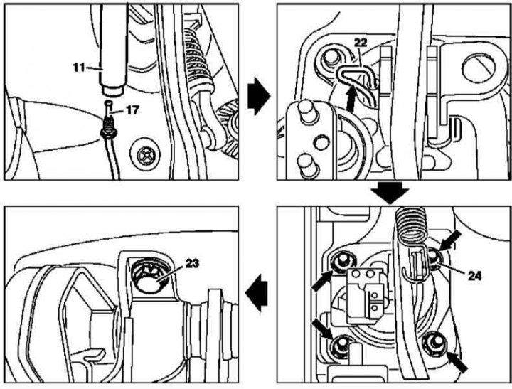
3. Remove the hose connecting the brake fluid reservoir to the GTZ (11).
4. Disconnect from GTZ (11) hydraulic line (17).
5. Disconnect the electrical wiring from the brake light switch.
6. If equipped, disconnect the electrical wiring from the clutch pedal sensor.
7. Disconnect the return spring from the foot brake pedal.
8. Remove the blocker (22) and remove the carrier bracket assembly from the brake pedal.
9. Give nuts (24) fixing the holder of the pedal assembly to the bulkhead of the engine compartment.
10. Turn out the top bolt (23) pedal mounts.
11. With the pedal assembly back, remove its baseplate from its mounting studs, then angle it out of the footwell.
12. If necessary, disassemble the pedal assembly.
13. Installation is carried out in the reverse order.
Brake light switch
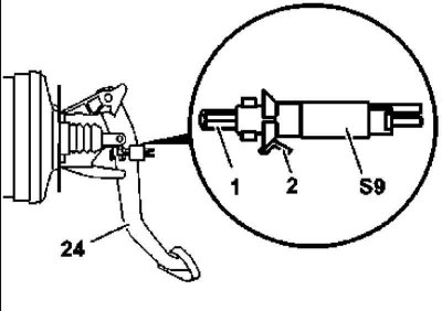
Details of installation of the gauge-switch of stoplights
1. The installation details of the brake light sensor-switch are shown in the illustration, to which all references in the text refer.
2. Remove the cover on the left under the instrument panel.
3. Disconnect from the brake light switch (S9) wiring.
4. Release the latch (2) and remove the switch (S9).
5. Pull out the plunger (1) sensor all the way out, depress the pedal (24) and install the sensor-switch in its regular place, making sure that the latch snaps into place (2), the adjustment of the sensor-switch occurs automatically.
6. Further installation is carried out in the reverse order to the dismantling of the components.