
Replacing the air cleaner element
Installation Details for Air Inlet Components on Models Equipped with 612 Series Engine
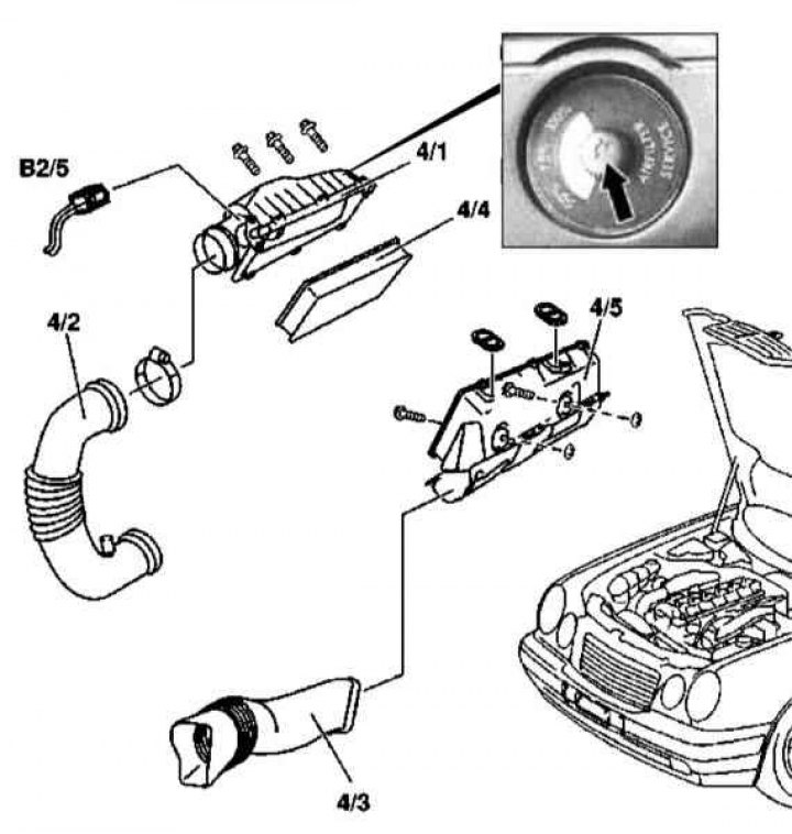
1. Illustrative material for replacing the air cleaner element on models 163.113 (612 series engine) presented in the illustration, which includes all references in the text.
2. Remove panels of finishing of a cover of a head of cylinders.
3. Disconnect the electrical wiring from the MAF sensor (B2/5).
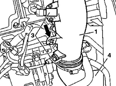
4. Disconnect the air hose from the air cleaner (4/2).
5. Remove the air intake (4/3).
6. Turn out fixing bolts and remove the top section of a casing of an air cleaner (4/1).
7. Remove filter element (4/4).
8. If necessary, remove the lower section of the air cleaner housing (4/5), - pay attention to the bottom (from the engine side) washers.
9. Installation is carried out in the reverse order - do not forget to replace the failed mounting clamps.
10. Finally, reset the indicator of the degree of contamination of the filter element (arrow).
Removal and installation of the intake air temperature sensor (IAT)
IAT sensor installation details on models 163.113 (612 series engine)
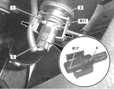
1. IAT sensor installation details on models 163.113 (612 series engine) shown in the illustration, which includes all references in the text.
2. Cut the bandage (1) holder fixation (3).
3. Disconnect the electrical wiring connector (2) IAT sensor (B17).
4. Press the mounting brackets together (arrows) and release the sensor (B17) from the holder (3).
5. Remove the O-ring (4), which must be replaced during assembly without fail.
6. Installation is carried out in the reverse order.
Attention! The sensor must be installed with the connector disconnected, otherwise the mounting brackets may be damaged (arrows) as a result of their pulling!
7. Finally, clear the memory of the on-board self-diagnosis system (see chapter Engine Electrical Systems).
Removal and installation of a turbocharger
Details of installation of a turbocharger on models 163.113 (612 series engine)
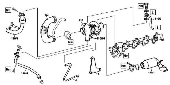
1. Turbocharger installation details on models 163.113 (612 series engine) shown in the illustration, which includes all references in the text.
2. Remove the bottom section of soundproofing.
3. Remove the air cleaner (see above).
4. Remove the air sleeve (4/2).
5. Disconnect from the turbocharger (110) duct (110/6).
6. Disconnect from the vacuum block (110/10) hose (4).
7. Loosen the oil supply line (110/3) from the turbocharger and the engine block, - hold the turbocharger from turning when loosening the union nut.
8. Remove primary catalytic converter (120/1).
9. Unscrew the support bracket from the crankcase (3).
10. Remove the turbocharger (110) complete with bracket (3) and oil lines (110/4).
11. Disconnect from the turbocharger (110) support bracket (3) and oil line (110/4), - prepare to collect spilled oil.
12. Installation is carried out in the reverse order. Be sure to replace all sealing elements. Tighten the union nuts of the oil lines only after installing the turbocharger.
13. In conclusion, check the level of impellent oil, if necessary, make the appropriate adjustment (see chapter Changing the engine oil and oil filter).
Removal and installation of an intermediate cooler of a path of pressurization of air
Details of installation of the intermediate cooler of a path of pressurization of air on models 163.113 (612 series engine)
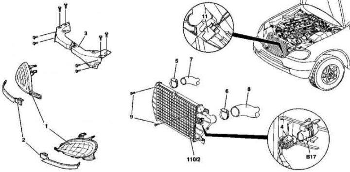
1. Details of installation of the intercooler of the charge air path on models 163.113 (612 series engine) shown in the illustration, which includes all references in the text.
2. Open the hood and lock it in an upright position.
3. Remove headlights (1) with overlays (2).
4. Remove the front cross member of the frame (3).
5. Disconnect the electrical wiring connector (4) IAT sensor (B17).
6. Release the fixing straps (5 and 6) and disconnect from the cooler heat exchanger (110/2) air sleeves (7 and 8).
7. Turn out fixing bolts (9) and remove the cooler (110/2).
8. Installation is carried out in the reverse order.
Removal and installation of the air distributor
Details of installation of the air distributor on models 163.113 (612 series engine)
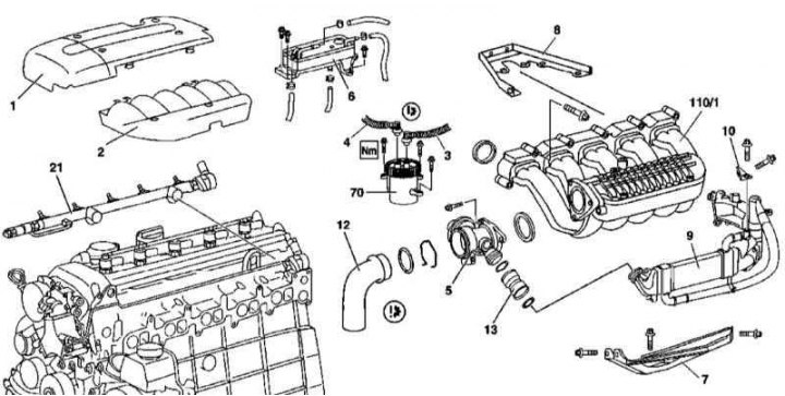
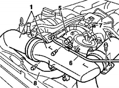
1 - Panel trim cylinder head cover; 2 - Air distributor finishing panel; 3 - Fuel supply line; 4 - Outlet fuel line; 5 - Mixing chamber; 6 - Fuel cooler; 7 - Lower support bracket of the air distributor; 8 - Upper support bracket of the air distributor; 9 - EGR cooler; 10 - EGR cooler support bracket on the air distributor pipeline; 12 - Air duct; 13 - Connecting pipe; 21 - Fuel line; 70 - Full flow fuel filter; 110/1 - Air distributor pipe
1. Installation details of the air distributor of the air boost path on models 163.113 (612 series engine) shown in the illustration, which includes all references in the text.
2. Open the hood and lock it in an upright position.
3. Remove powertrain trim panels (1 and 2).
4. Remove the bottom section of the soundproofing.
5. Disconnect the negative cable from the battery.
6. Empty the cooling system (see chapter Checking the cooling system and frost resistance of the coolant, changing the fluid).
7. Remove the fuel cooler (6).
8. Remove the fuel line (21) (see Section Removal and installation of the fuel distributive highway and nozzles).
9. Remove the fuel line support brackets.
10. Unbolt the top support bracket (8) air distributor (110/1).
11. Pump out the oil from the power steering reservoir and disconnect the hydraulic hose from the latter - immediately plug the open ends of the hose and fitting.
12. Disconnect the vacuum lines.
13. Remove the radiator overflow hose.
14. Remove connected to the mixing chamber (5) duct (12).
15. Remove the mixing chamber (5).
16. Remove the connecting pipe (13).
17. Remove the thermostat cover (see chapter Cooling, heating and air conditioning systems).
18. Remove the support bracket (10) fastenings on the pipeline of the air distributor of a tube of system EGR.
19. Release the harness from the clamps, laid along the distribution pipeline (110/1), - disconnect the contact connectors of the oil level sensors (B40), CKP (L5), boost pressure (B28), inlet port locking limit switch (S99) and starter motor (M1).
20. Turn out fixing bolts and remove the pipeline of the air distributor (110/1) from bottom support bracket (7).
21. Installation is carried out in the reverse order - do not forget to replace the sealing elements and failed components.
22. Finally, clear the memory of the on-board self-diagnosis module (see chapter Engine Electrical Systems).
Removal and installation of the electric motor of the actuator for blocking the intake port
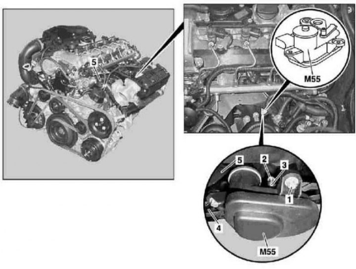
Details of installation of the electric motor of the executive device of blocking the inlet port on models 163.113 (612 series engine)
1. Details of installation of the electric motor of the drive of overlapping of the inlet port on models 163.113 (612 series engine) shown in the illustration, which includes all references in the text.
2. On models with AT, remove the air distributor (see above).
3. On models with manual transmission, remove the left front wheel and wheel arch protection locker.
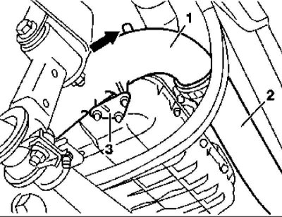
4. Turn out bolts (1).
5. Release the lock and carefully remove the support (3) with ball head (2).
6. On models with a manual transmission, disconnect the electrical wiring connector (4) electric motor (M55).
7. Remove the electric motor (M55) from air distributor assembly (5).
8. Installation is carried out in the reverse order. Check that all positioning flaps fit correctly and that they move smoothly. Don't forget to replace the sealing elements.
9. Finally, clear the memory of the on-board self-diagnosis module (see chapter Engine Electrical Systems).
Models 163.128
Replacing the air cleaner element
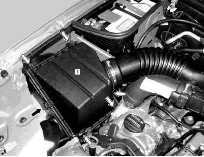
Design of the air cleaner models 163.128 (628 series engine)
1. Illustrative material for replacing the air cleaner element on Models 628 (628 series engine) presented in the illustration, which includes all references in the text.
2. Remove the brackets of the six retainers (arrows) air cleaner cover (1).
3. Remove the cover (1) and remove the filter element to be replaced from the air cleaner housing.
4. Installation is carried out in the reverse order - follow the correct fit of the cover.
Removal and installation of the intake air temperature sensor (IAT)
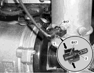
IAT sensor installation details on models 163.128 (628 series engine)
2 - O-ring
1. IAT sensor installation details on models 163.128 (628 series engine) shown in the illustration, which includes all references in the text.
2. Open the hood.
3. Remove the engine intake fan sleeve from the front of the air cleaner.
4. Disconnect the wiring connector (1) sensor (B17), simultaneously fixing the mounting brackets (arrows) the last one.
Removal and installation of turbochargers
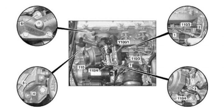
Installation details of the right turbocharger on models 163.128 (628 series engine)
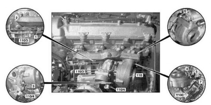
Installation details of the left turbocharger on models 163.128 (628 series engine)
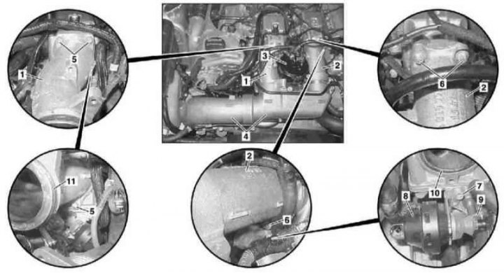
1. Details of installation of turbochargers on models 163.128 (628 series engine) shown in the illustrations, which include all references in the text.
2. Remove the front wheels and wheel arch protectors.
3. Remove the inlet ducts from both (right/left) air intake paths (see below).
4. Remove the bottom air ducts of both (right and left) air intake paths (see below).
5. Give the nut (1) on oil line support bracket (110/3).
6. Remove the bolt (2) and disconnect the oil supply line (110/3) from the cylinder head.
7. Disconnect the oil supply line (110/3) from the left turbocharger (110).
8. Turn out bolts (3) and disconnect the oil return line (110/4) from the turbocharger and crankcase.
9. Release the clamp securing the primary catalytic converter to the right turbocharger (110).
10. Fully loosen and pull back the left three-function catalytic converter (TWC).
11. Remove the bolt (4) on support bracket (5).
12. Disconnect from the turbocharger (110) boost pressure regulator wiring (7).
13. Turn out fixing bolts (6) and remove the turbocharger (110) from the engine exhaust manifold.
Attention! Boost pressure regulators (Y100 and Y100/1) must only be replaced in conjunction with the appropriate turbocharger!
14. Installation is carried out in the reverse order. Be sure to replace all sealing elements. Tighten the union nuts of the oil lines only after installing the turbocharger.
15. In conclusion, check the level of impellent oil, if necessary, make the appropriate adjustment (see chapter Changing the engine oil and oil filter).
Removal and installation of an intermediate cooler of a path of pressurization of air
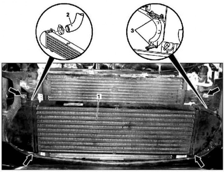
Details of installation of the intermediate cooler of a path of pressurization of air on models 163.128 (628 series engine)
1. Details of installation of the intercooler of the charge air path on models 163.128 (628 series engine) shown in the illustration, which includes all references in the text.
2. Open the hood and lock it in an upright position.
3. Remove both headlights.
4. Remove the upper front cross member of the frame.
5. Disconnect from the right side of the cooler (1) air sleeve (2).
6. Remove the screws securing the connecting plates (3) on the left side of the cooler heat exchanger (1).
7. Remove the fixing screws (arrows) and remove the cooler (1).
8. Installation is carried out in the reverse order - do not forget to replace the sealing elements.
Removal and installation of the air distributor
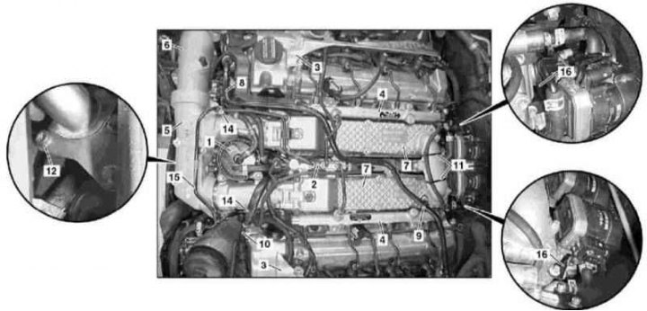
Details of installation of the air distributor on models 163.128 (628 series engine)
Details of installation of the air distributor on models 163.128 (628 series engine)
1. Installation details of the air distributor of the air boost path on models 163.128 (628 series engine) shown in the illustrations, which include all references in the text.
2. Remove the fuel filter (1) complete with support bracket.
3. Remove the valve block (2).
4. Remove the pads (3) cylinder head covers and disconnect the oil drain pipes from the injectors.
5. Remove fuel lines (4).
6. Remove bypass ducts (5), - only for the lower section (6), - air ducts (5) removed as an assembly with the upper sections of the air distributor (7).
7. Disconnect the line from the vacuum pump (8), remove and slide the bracket to the side (9).
8. Disconnect the vacuum line (10) inlet port check valve.
9. Remove the bandage (11) fixation of the transport pipeline.
10. Turn out bolts (12).
11. Turn out bolts (13) EGR cooler mounts.
12. Disconnect from the line (15) coolant hoses (14).
13. Remove and lay aside the line of the cooling path (15).
14. Remove the support brackets (16) left and right EGR positioners.
15. Turn out fixing bolts (17) and remove the upper sections of the air distributor (7) complete with sleeves (5).
16. Installation is carried out in the reverse order - do not forget to replace the sealing elements and failed components.
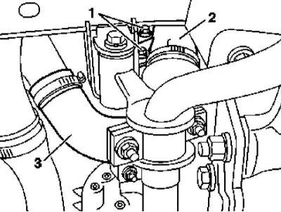
Removal and installation of inlet sleeves of a path of pressurization of air
Details of installation of the left inlet sleeve of a path of pressurization of air on models 163.128 (628 series engine)
Details of installation of the right inlet sleeve of a path of pressurization of air on models 163.128 (628 series engine)
1 - Inlet sleeve; 2 - Bolt; 3 - Hose clamp; 4 - Bolt; 5 - Lid
Details of installation of inlet sleeves of a path of pressurization of air on models 163.128 (628 series engine) shown in the illustrations, which include all references in the text.
Left sleeve
1. Remove the left front wheel and wheel arch locker.
2. Disconnect the intake hose from the air distributor.
3. Turn out bolts (2) flange (3).
4. Remove the bolt (5) on the cylinder head cover.
5. Release clamp (4) and remove the intake manifold (1).
6. Installation is carried out in the reverse order.
Right sleeve
1. Disconnect the intake hose from the air distributor.
2. Disconnect the electrical wiring from the boost pressure sensor.
3. Remove the bolt (2) on the cylinder head cover.
4. Release clamp (3) and remove the intake manifold (1).
5. Installation is carried out in the reverse order.
Removal and installation of the lower sleeves of a path of pressurization of air
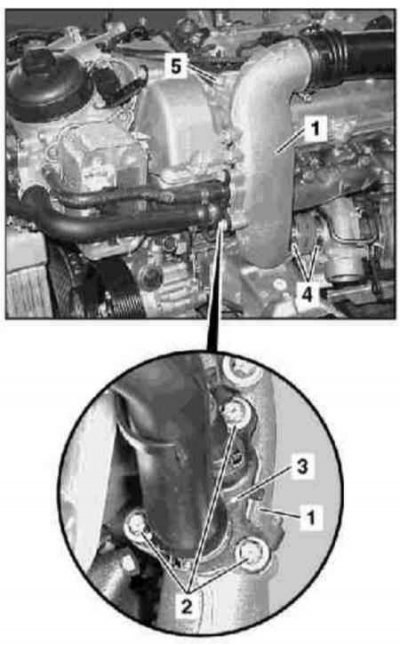
Details of installation of the left lower sleeve of a path of pressurization of air on models 163.128 (628 series engine)
Details of installation of the left lower sleeve of a path of pressurization of air on models 163.128 (628 series engine)
Details of installation of the right lower sleeve of a path of pressurization of air on models 163.128 (628 series engine)
Details of installation of the right lower sleeve of a path of pressurization of air on models 163.128 (628 series engine)
Details of the installation of the lower sleeves of the air pressurization path on models 163.128 (628 series engine) shown in the illustrations, which include all references in the text.
Left sleeve
1. Remove the bottom section of the soundproofing.
2. Remove air intake hose (3).
3. Turn out bolts (1).
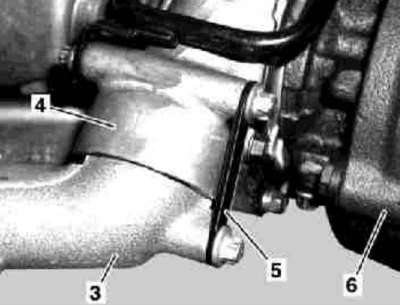
4. Loosen the top screw of the connection plate (5) on the inlet flange (4) turbocharger (6).
5. Remove the bottom screw of the plate (5) on the air sleeve (2).
6. Detach the sleeve (2) from the flange (4) turbocharger (6) and remove it from the engine by lowering it down.
7. Installation is carried out in the reverse order - do not forget to replace the sealing ring.
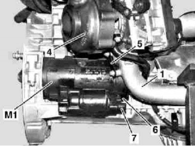
Right sleeve
1. Disconnect the negative cable from the battery.
2. Remove the bottom section of the soundproofing.
3. Remove the protective covers of electrical lines (6 and 7) starter (M1), - terminals No. 30 and 50.
4. Turn out bolts of fastening of a starter to a dome of transmission.
5. Loosen the top screw of the connection plate (5) on the intake flange of the turbocharger (4).
6. Remove the bottom screw of the plate (5) on the air sleeve (1).
7. Detach the sleeve (2) duct (1).
8. Remove the support brackets (3) from the lower section of the oil pan and from the air duct (1).
9. Remove the top bracket (arrow) air duct from the engine crankcase.
10. Set aside the starter and ATF lines and disconnect the air hose from the turbocharger inlet flange.
11. Pass the sleeve forward and remove it from the engine compartment.
12. Installation is carried out in the reverse order - do not forget to replace the sealing ring.
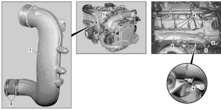
Removal and installation of bypass ducts
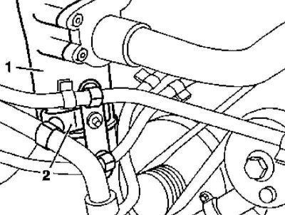
Installation details for bypass ducts on models 163.128 (628 series engine)
1 - Bypass duct
2 - Support brackets for the cooling path lines
Installation details for bypass ducts on models 163.128 (628 series engine)
1 - Bypass air duct; 3 - Sensor; 4 - Air sleeve
Installation details for bypass ducts on models 163.128 (628 series engine)
1 - Bypass air ducts; 5 - Right connecting pipe; 6 - Hydraulic line power steering; 7 - Left connecting pipe; 8 - EGR line
1. Installation details of bypass ducts on models 163.128 (628 series engine) shown in the illustrations, which include all references in the text.
2. Remove powertrain trim panels.
3. Disconnect wiring from sensor (3).
4. Release the cooling path lines from the bracket (2).
5. Detach the air sleeve (4) from the bypass sleeve (1).
6. Separate the power steering line from the air hose (6).
7. Separate the EGR pipe (8) from the connecting flange of the cylinder head (arrow).
8. Disconnect the bypass sleeves from the connecting pipes (5 and 7) and remove them from the engine.
9. Installation is carried out in the reverse order - do not forget to replace the sealing elements.
Removal and installation of intermediate connecting pipes
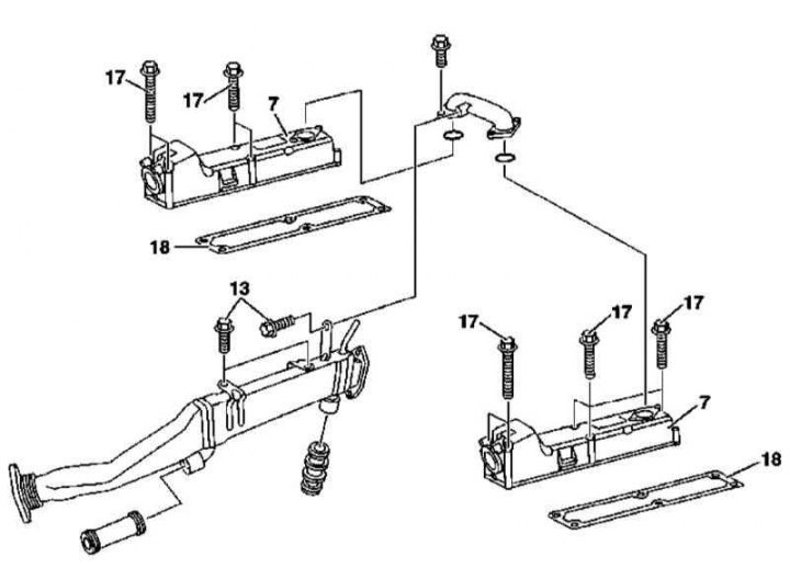
Installation Details for 628 Series Intermediate Air Path Connections
1 - Right connecting pipe; 2 - Left connecting pipe; 3 - Fuel filter; 4 - Throttle valve positioner with upper air sleeves; 5 - Screw; 6 - Screw; 7 - Screw; 8 - Vacuum block for blocking the inlet port; 9 - Thrust; 10 - O-ring; 11 - O-ring
1. Details of installation of intermediate air ducts on models 163.128 (628 series engine) shown in the illustration, which includes all references in the text.
2. Lift the power package cover.
3. Remove bypass ducts (see above).
4. Remove the fuel filter (3).
5. Remove the screws (5) and remove the right connecting pipe (1).
6. Disconnect the rod (9) vacuum block blocking the inlet port (8).
7. Remove the screw (7) and set aside the vacuum block (8).
8. Remove the screws (6) and remove the left connecting pipe (2).
9. Install in reverse order - do not forget to replace the O-rings (10 and 11).