
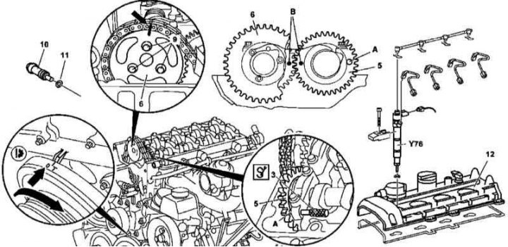
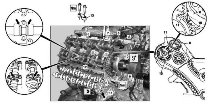
Details of installation of camshafts of the 612 series engine
3 - Locking rod; 5 - Intake camshaft gear; 6 - Camshaft drive sprocket; 10 - Chain tensioner; 11 - Sealing element; 12 - Cylinder head cover; A - Hole in the gear of the intake camshaft; B - Mounting marks; Y76 - Nozzle
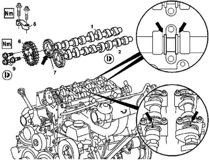
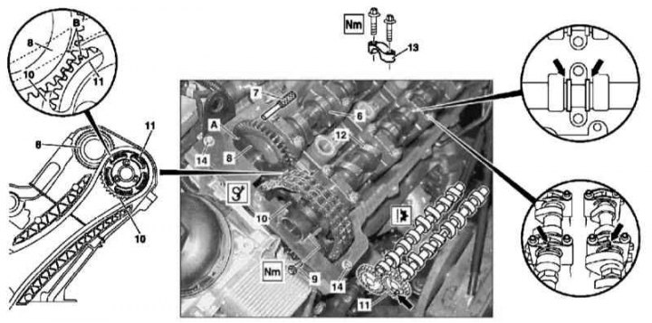
Details of installation of camshafts of the 612 series engine
1 - Final camshaft; 2 - Intake camshaft; 6 - Camshaft drive sprocket; 7 - Guide pin; 8 - Camshaft bearing cap; 9 - Bolts for fastening the sprocket
The details of installing camshafts on 612 series engines are shown in the illustrations, which include all references in the text.
Removing
1. Remove the cylinder head cover trim panels.
2. Remove nozzles (Y76).
3. Remove the cylinder head cover (12).
4. Turning the crankshaft in the normal direction, bring the engine to the TDC position of the piston of the first cylinder - the marks on the bodies of the camshafts and bearing caps must be aligned (arrows).
5. Block the intake camshaft (2), passing through a special rod (3) through the bearing cover and inserting it into the hole (A) drive gear (5).
6. Remove chain tensioner (10) (see Section Removal and installation of timing drive components).
7. Remove the front cylinder head cover (see Section Removing and installing timing covers).
8. Remove the top chain guide (see Section Removal and installation of timing drive components).
9. Mark the position of the chain on the camshaft sprocket (6).
10. Screw off the asterisk (6) and remove it from the exhaust camshaft stub (1).
11. Having previously marked, remove the camshaft bearing caps (8).
12. Carefully remove the camshafts (1 and 2) from the cylinder head.
Installation
1. Install the camshafts in their regular places in the cylinder head - follow the requirements of the basic installation (see Section Setting the basic position of the camshafts).
2. Bring the engine to a position of 30°before TDC of the piston of the first cylinder.
3. Referring to the markings made during dismantling, reinstall the bearing caps (8).
4. Block the intake camshaft (2) rod (3).
5. Fit the drive sprocket (6) on the exhaust camshaft (1).
6. Install chain tensioner (10).
7. Make sure that the requirements of the basic installation of camshafts are observed (see Section Setting the basic position of the camshafts).
8. Install the cylinder head cover (12).
9. Clean and install nozzles (Y76) (see chapter Removal and installation of the fuel distributive highway and nozzles).
10. Establish panels of furnish of a cover of a head of cylinders.
11. Start the engine and check it for signs of leak development.
12. Finally, clear the memory of the on-board self-diagnosis module (see chapter Engine Electrical Systems).
End caps for camshafts
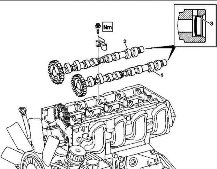
Details of installation of end caps of camshafts of diesel engines of series 612 and 628
1. The installation details of the camshaft end caps are shown in the illustration, to which all references in the text refer.
2. Remove the camshafts (1 and 2) (see above).
3. Using a suitable screwdriver, remove the cover (3) from the end of the rear camshaft pin - try not to damage the walls of the seat.
4. Clean and degrease the cover installation slot.
5. Using a suitable drift, seat the new end cap into the shaft stub to the desired depth.
Attention! An excessively deep seating of the cover can lead to blockage of the oil supply!
6. Install the camshafts in the cylinder head (see above).
M628
Camshafts
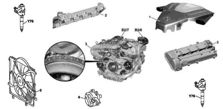
Details of installation of camshafts of the 628 series engine
1 - Air cleaner; 2 - Cylinder head cover; 3 - Throttle valve positioner with an upper air duct; 4 - Vacuum pump; 5 - Casing of the fan assembly; В2/6 - Left MAF sensor; В2/7 - Right MAF sensor; Y76 - Nozzle
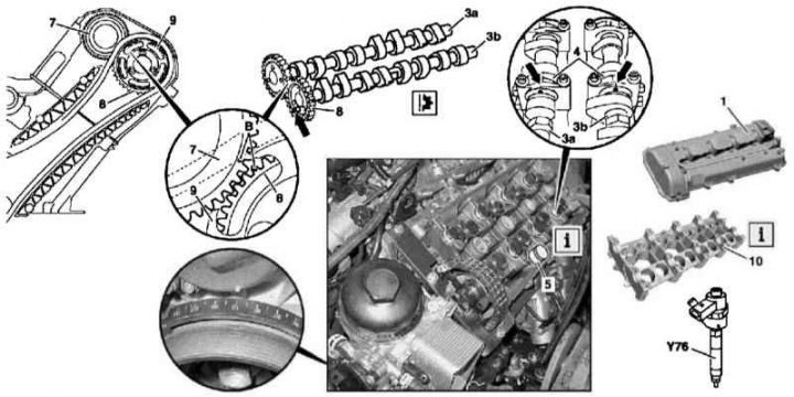
Details of installation of camshafts of the 628 series engine (right cylinder head)
6 - Intake camshaft; 7 - Locking rod; 8 - Intake camshaft gear; 9 - Bolt; 10 - Drive sprocket; 11 - Gear wheel of a final camshaft; 12 - Final camshaft; 13 - Camshaft bearing cap; A - Hole; B - Marking
Details of installation of camshafts of the 628 series engine (left cylinder head)
The details of installing camshafts on 628 series engines are shown in the illustrations, which include all references in the text.
Removing
1. Disconnect the air distributor.
2. Disconnect the inlet sleeve of the charge air path from the cylinder head and turbocharger and press it to the side.
3. Remove the nozzle cover.
4. Remove nozzles (Y76).
5. Remove the cover (2) corresponding cylinder head.
6. Remove the bypass sleeve of the air boost path.
7. Remove the vacuum pump (4).
8. Having turned the crankshaft in the normal direction, bring the engine to the TDC position of the piston of the first cylinder - the marks on the bodies of the camshafts and their covers must be aligned.
9. Block the intake camshaft (6), passing through the rod (7) through the cover of the first bearing and tucking it into the hole (A) in the drive gear (8).
10. When working on the right head, acting through the window in the front cover, seat the holder on the camshaft drive sprocket (10). On the left head, a special holder is mounted on the cylinder head, sits on the drive sprocket (10) and fixed with screws (14) cylinder head covers.
11. Separate the drive sprocket (10) from the exhaust camshaft stub (12).
12. Remove covers (13) camshaft bearings (6 and 12) and remove the latter from the cylinder head, - leave the sprocket fixed in the holder.
Installation
1. Lay the camshafts in their regular places in the cylinder head - follow the requirements of the basic installation (see Section Setting the basic position of the camshafts).
2. Align the camshafts on the thrust bearings (arrow).
3. With a rod (7) block intake camshaft (6).
4. Attach the sprocket (10) to the exhaust shaft (12).
5. Make sure the basic installation requirements are met (see Section Removal and installation of timing drive components).
6. Further installation is carried out in the reverse order to the dismantling of the components.
7. Start the engine and check it for signs of leak development.
8. Finally, clear the memory of the on-board self-diagnosis module (see chapter Engine Electrical Systems).
End caps for camshafts
1. The installation details of the camshaft end caps are shown in resist. an illustration to which all references in the text refer.
2. Remove the camshafts (1 and 2) (see above).
3. Using a suitable screwdriver, remove the cover (3) from the end of the rear camshaft pin - try not to damage the walls of the seat.
4. Clean and degrease the cover installation slot.
5. Using a suitable drift, seat the new end cap into the shaft stub to the desired depth.
Attention! An excessively deep seating of the cover can lead to blockage of the oil supply!
6. Install the camshafts in the cylinder head (see above).
Bed of camshafts
Details of installation of bed of camshafts of the engine of a series 628
1 - Cylinder head cover; 3a - Intake camshaft; 3b - Exhaust camshaft; 4 - Camshaft bearing caps; 5 - Valve clearance compensators; 7 - Intake camshaft gear; 8 - Gear wheel of a final camshaft; 9 - Camshaft drive sprocket; 10 - Bed of camshafts; B - Mounting marks; Y76 - Injectors
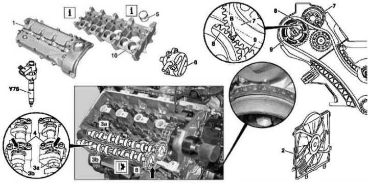
Details of installation of bed of camshafts of the engine of a series 628
2 — Casing fan assembly
1. The details of installing the bed of the camshafts of the 628 series engine are shown in the illustrations, which include all references in the text.
2. Remove the air distributor.
3. Remove the camshafts (3a and 3b) (see above).
4. Fasten the pushers equipped with hydraulic lifters in their seats (5) valves.
Note. Alternatively, the pushers can be removed from the bed of the shafts, however, a magnet should not be used for this purpose - magnetization of the pushers is fraught with the accumulation of metal filings on them!
5. Remove the bed of camshafts (10).
6. Installation is carried out in the reverse order.
7. Start the engine and check it for signs of leak development.
8. Finally, clear the memory of the on-board self-diagnosis module (see chapter Engine Electrical Systems).