



Contents: Front axle ↡ Rear axle ↡
Front axle
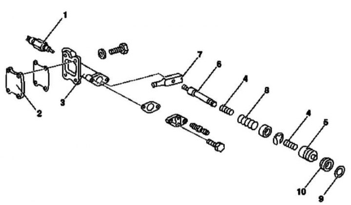
Design of the actuator cylinder of the front axle interwheel differential lock drive
1 - Pressure switch sensor; 2 - Lid; 3 - Cylinder; 4 - Springs; 5 - Piston; 6 - Rod; 7 - Lever; 8 - Compression spring; 9 - Sealing ring; 10 - Dust cover
1. Remove the pressure switch sensor (1).
2. Unscrew the cover (2).
3. Remove the piston (5) with springs (4).
4. Unbolt the rod (6) from the lever (7) and remove it together with the compression spring (8).
5. Carefully wipe the removed components, replace defective parts.
6. After lubricating the sliding surfaces with a light silicone grease such as Molykote 44, place the compression spring (8) on the rod. Use Loctite 241 grease to lubricate the threaded part of the rod.
7. Insert the rod (6) together with the compression spring (8) into the cylinder (3) and screw it into the lever (7).
8. Install a NEW sealing ring (9) and a NEW boot (10).
9. Insert the piston (5) with springs (4) into the cylinder.
10. Screw on the cover (2).
11. Install the pressure switch sensor (1).
Rear axle
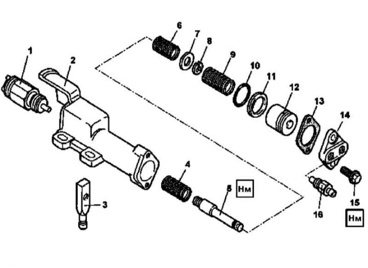
Design of the actuator cylinder of the rear axle interwheel differential lock drive
1 - Pressure switch sensor; 2 - Cylinder casing; 3 - Shift lever; 4 - Sensor-switch spring; 5 - Rod; 6 - Return spring; 7 - Washer; 8 - Retaining ring; 9 - Compression spring; 10 - Dust cover; 11 - Sealing element; 12 - Pistons; 13 - Sealing gasket; 14 - Lid; 15 - Bolts; 16 - Bleed valve
1. Remove the pressure switch sensor (1).
2. Unscrew the bolts (15) and remove the cover (14), - prepare a replacement sealing gasket (13).
3. Remove the piston (12) with the compression spring (9), prepare the replacement sealing element (10) and dust cover (11).
4. Unscrew the rod (5) from the lever (3) and release both elements, as well as the switch-sensor spring (4) from the cylinder casing (2).
5. Disassemble the rod (5) - to make the procedure easier, screw the lever (3) onto the rod and clamp it in a vice with soft jaws.
6. Carefully wipe the removed components, replace defective parts.
7. Assemble the rod - the retaining ring (8) must be securely fixed in the receiving groove.
8. Installation is carried out in the reverse order, - NEW sealing elements should be lubricated with silicone grease before installation. To lubricate the threaded part of the rod (5), use Loctite 270 grease (about 10 material).