



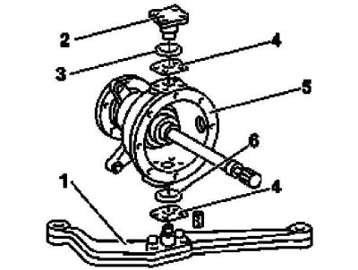
Construction of the rotary unit
1 - Pivot lever; 2 - Upper wheel pivot bolt; 3, 6 - Distance rings; 4 - Adjusting washers; 5 - Hinged casing
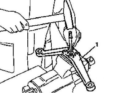
Centering the Pivot Lever (1)
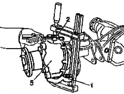
Measuring the gap size "A" in the upper rotary unit
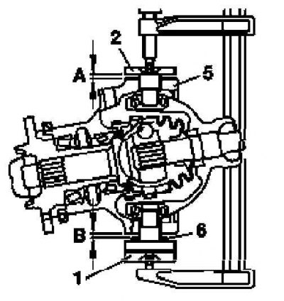
Rotary assembly diagram for calculating the thickness of the adjusting washers
1. Remove the hinge housing assembly with the drive shaft (see Section Removal and installation front axle drive shafts).
2. Insert the appropriate guide ring from the special repair kit into the axle housing sleeve - the ring should press against the bearing race without any play.
3. If necessary, center the pivot arm (1) using a center punch.
4. Install the upper wheel pivot bolt (2) with the 2mm spacer ring (3) and without the adjusting washer (4).
Note: The bottom bolt is pre-tensioned into the pivot housing assembly (5) for the last five millimetres, so a 6 mm thick spacer ring must be installed between it and the inner bearing race before measuring the adjusting washers. Another 4 mm thick ring must be installed between the pivot arm and the pivot housing.
5. Insert the bolt into the lever enough to completely remove any play in the swivel bearing.
6. To seat the bearing, rotate the hinge housing in different directions.
7. Using a blade-type feeler gauge, measure the gap "A" between the casing (5) and the bolt (2), then using the spacer ring (6), determine the gap "B" between the casing (5) and the pivot arm (1), - record the measurement results.
8. Calculate the thickness of the adjusting washers according to the following diagram:
Upper swivel joint
- Gap "A" = 1.30 mm
- Adjusting ring = 2.00 mm
- Bearing preload = 0.15 mm
- Calculated thickness of the adjusting washer = 2.00 - 1.30 + 0.15 = 0.85 (mm)
Lower swivel joint
- Gap "B" = 1.10 mm
- Difference in thickness of spacer rings = 6 - 4 = 2.00 (mm) (see note above)
- Bearing preload = 0.15 mm
- Calculated thickness of the adjusting washer = 2.00 - 1.10 + 0.15 = 1.05 mm
9. Remove the guide ring and install the hinge housing assembly into place with the drive shaft (see Section Removal and installation front axle drive shafts).
10. Further installation is carried out in the reverse order of dismantling the components.