



Contents: Front axle ↡ Rear axle ↡
Front axle
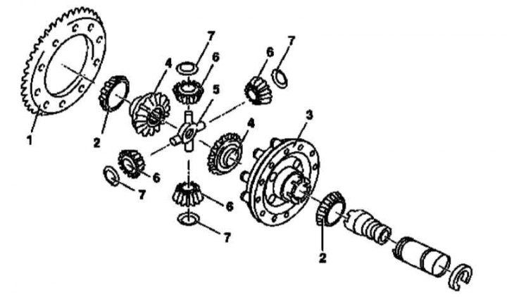
Front axle interwheel differential design
1 - Driven gear of the main transmission; 2 - Tapered roller bearings; 3 - Differential box; 4 - Side gears; 5 - Crosspiece; 6 - Satellites; 7 - Spherical washers
1. Remove the differential assembly with the final drive driven gear (see Section Removal and installation of interwheel differential assemblies with driven gears of final drives).
2. Loosen the mounting bolts and remove the driven gear (1).
3. Using a suitable puller, remove the tapered roller bearings (2).
Text republished from the website (www.mercedesman.ru)
4. Remove the cover from the differential box (3), - mark the position of the spherical washers, gears and crosspiece relative to each other and relative to the box. Also mark the position of the cover relative to the box.
5. Remove one of the side gears (4) with the adjusting washer.
6. Remove the crosspiece assembly (5) with the satellites (6).
7. Remove the satellites (6) with spherical washers (7).
8. Remove the second side gear (4).
9. Carefully wipe the removed components, replace defective parts.
10. Installation is performed in the reverse order - the adjusting washers must be turned with the grooves towards the side gears. Make sure that the installation marks applied during dismantling are correctly aligned. Before installing the tapered bearings, check the resistance of the side gears to rotation - if necessary, select replacement adjusting washers.
Note: Before pressing on, the bearings should be heated to a temperature of approximately 80°C - the bearings should fit flush with the differential gears.
Rear axle
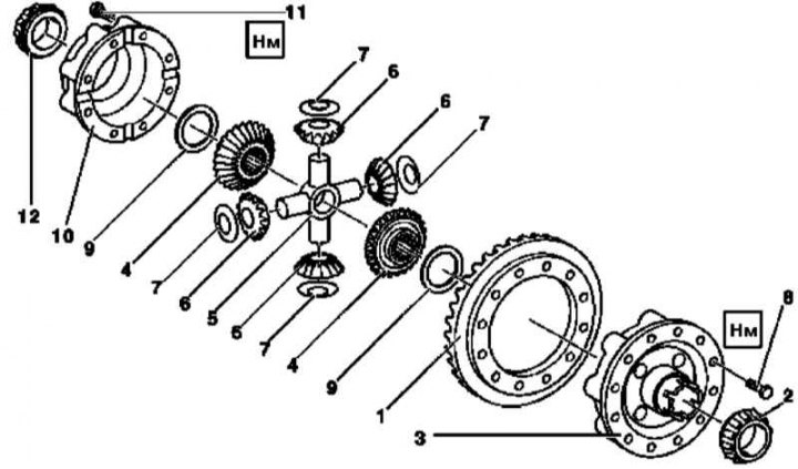
Rear axle interwheel differential design
1 - Driven gear of the main transmission; 2, 12 - Tapered roller bearings; 3 - Differential box; 4 - Side gears; 5 - Crosspiece; 6 - Satellites; 7 - Spherical washers; 8, 11 - Bolts; 9 - Thrust washers; 10 - Lid
1. Remove the differential assembly with the final drive driven gear (see Section Removal and installation of interwheel differential assemblies with driven gears of final drives).
2. Using a suitable puller, remove the tapered roller bearing (2) (from the driven gear side).
3. Unscrew the mounting bolts and remove the driven gear (1) from the box (3).
4. Using a suitable puller, remove the tapered roller bearing (12) (from the box side).
5. Having previously marked the installation position, separate the cover (10) from the box (3).
6. Remove the first side gear (4) with the thrust washer (9).
7. Remove the crosspiece (5) with the satellites (6) and spherical washers (7).
8. Remove the second side gear (4) with washer (9).
9. Carefully wipe the removed components, replace defective parts.
10. Installation is carried out in the reverse order - the adjusting washers must be turned with the grooves towards the side gears. Ensure that the alignment marks applied during dismantling are correctly aligned. Before installing the tapered bearings, check the differential's resistance to rotation (before pressing, the tapered bearings must be heated to a temperature of about 80°C - the bearings must be seated tightly against the differential gears).
Note: A thinner adjusting shim must be installed on the driven gear side to ensure sufficient engagement clearance.