



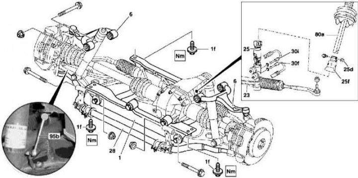
Front Axle Assembly Installation Details
1 - Subframe; 1f - Bolts; 6 - Upper wishbone; 23 - Steering gear; 25 - Steering rack input unit; 25d - Nut; 25f - Dust cover; 28 - Torsion bar; 30i - Hydraulic Pressure Hose; 30f - Return hydraulic line; 80a - Lower steering column shaft; 95b - Landing level regulator connecting rod
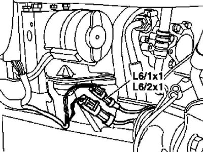
Front Axle Assembly Installation Details
L6/1x1 — Left wheel sensor wiring connector
L6/2x1 — Right wheel sensor wiring connector
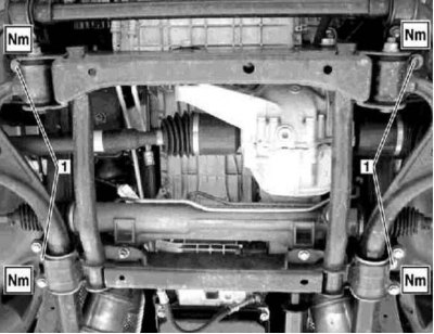
Front Suspension Subframe Installation Details
1 - Mounting bolts
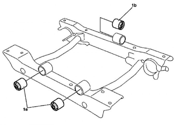
Layout diagram of transmission suspension supports on the subframe
1a, 1b - Rubber bushings
Note: All self-locking bolts and nuts must be replaced!
1. The installation details of the front axle assembly are shown in the illustrations to which all references in the text refer.
2. Remove the front wheels.
3. Remove the front shock absorbers (see Section Removal, checking and installation front shock absorbers).
4. Disconnect the wheel sensor wiring connectors (L6/1x1 and L6/2x1).
5. Disconnect the brake lines from the flexible brake hoses (see Chapter Brake and auxiliary systems).
6. Disconnect the propeller shaft from the front differential input flange (see Chapter Transmission line).
7. Remove the front suspension torsion springs (see Section Removal and installation torsion springs).
8. Remove the crankcase guard.
9. Disconnect the torsion hose (28) from the vehicle frame.
10. Disconnect the upper suspension arm (6) from the frame.
11. If equipped, remove the subframe support brackets for the ATF cooling lines.
12. Release the brake lines from the clips on the rear side of the subframe (1).
13. On models equipped with xenon headlights, disconnect the ride height adjuster rod (95b) from the right lower wishbone.
14. Pump out the hydraulic fluid from the power steering reservoir.
15. Turn the steering wheel to the straight-ahead position and lock it by removing the key from the ignition switch - turning the steering wheel with the steering column disconnected can damage the spiral contact drum of the horn circuit and the driver's airbag.
16. If equipped, disconnect the speed-sensitive power steering (SPS) wiring connector from the cylinder head cover.
17. Loosen the nuts (25d), remove the bolt and carefully release the lower steering column shaft (80a) from the steering gear input unit (25), - if necessary, slightly loosen the lock with a screwdriver.
Attention! Pull the shaft in a direction strictly parallel to its axis!
Note: Self-locking nuts (25d) must be replaced.
18. After loosening the union nuts/unscrewing the hollow bolts of the union connections, remove the pressure (30i) and return (30f) hydraulic lines of the power steering system - immediately seal the open ends of the union connectors.
19. Disconnect the ventilation hose from the differential housing.
20. Support the front axle subframe (1) and remove the self-locking bolts (1f) - the bolts must be replaced without fail.
21. Having moved all the hoses to the sides, lower the bridge assembly.
22. If necessary, remove the subframe and replace the rubber cushions of the transmission suspension supports; the bushings are removed/installed using a special extractor.
23. Installation is carried out in the reverse order - final tightening of the transverse lever fastening elements is carried out only after the car has been lowered to the ground. When connecting the steering shaft, the rack and pinion gear must be in neutral (rectilinear) position. Do not forget about the need to replace the sealing elements of the nipple connectors of the hydraulic lines.
24. Finally, adjust the levels of the brake and power steering fluids, and remove air from the hydraulic lines.
25. Correct the direction of the optical axes of the headlights and adjust the suspension geometry.
Full article available on the resource Mercedesman.ru