
The front wheel suspension mechanism consists of shock absorber struts with built-in shock absorbers, lower transverse wishbones, anti-roll bar (not on all models) and transverse leaf spring. Connecting rods are installed on both sides between the ends of the anti-roll bar and the upper surface of the axle carrier beam. Rubber bushings are installed at both ends of the rods, which are put on the ends of the stabilizer and the neck of the beam without a threaded connection. The stabilizer is attached to the bottom of the body.
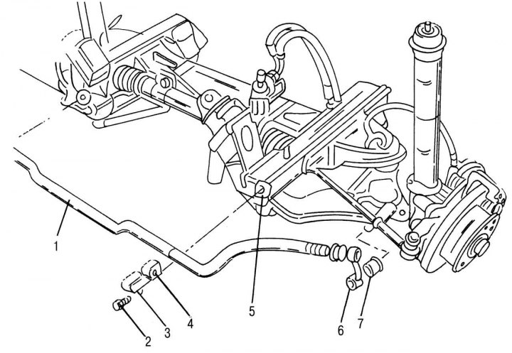
Pic. 197. The device of the front axle assembly: 1 - stabilizer bar; 2 - bolt; 3 — a clip of the stabilizer of cross-section stability; 4 - rubber-metal support (lubricate with oil when replacing); 5 - nut, 25–28 Nm; 6 - connecting rod; 7 - rubber-metal bushings of the connecting rod (lubricate with oil when replacing)
Both transverse levers are attached to the frame with their back side, and in front they are connected through a turnable ball joint to the hub housing and the steering knuckle. The shock absorber struts are attached to the hub mechanism with four bolts. The upper end of the shock absorber is screwed to the car body. On fig. 197 shows what the front suspension mechanism looks like. Depending on the modification, different types of front axles are installed on cars. Front axle VL 0/6 CE-1.6 is installed on models 208D and 212D series 901 and 902 (designation 730.408). However, these models can also be fitted with an axle with designation 730.410. Models 308D and 312D of the 903 series are equipped with a VL 0/7 CE-1.6 axle with designation 730.409. Model 412D is equipped with a VL 0/8 CE-1.75 bridge with designation 730.411. This data is required when purchasing spare parts.