
Note. Separate characteristics are also given in the text of the Chapter and, if they are mandatory, are highlighted in bold.
| Type | 5-speed, with electronically controlled gear shifting. |
| Designation | |
| S280 | (W5A330) 722.617 |
| S320 | (W5A330) 722.618 |
| S430 | (W5A580) 722.632 |
| S500, S55AMG | (W5A580) 722.633 |
| S600 | (W5A580) 722.649 |
| Gear ratios and engagement of AT elements | |
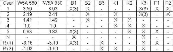 | |
| (1) Program switch in position S | |
| (2) Program switch in position W | |
| (3) Shift actuators only when coasting | |
| W5A 580, Final drive | 2.82 |
| W5A 330, Final drive | 3.07 |
| Fluid used | |
| S 280, S 320 | 7.0 l, MB No. 001 989 21 03 10 |
| S 420, S 500, S 600 | 9.0 l, MB No. 001 989 21 03 10 |
| Diagnostic codes for the automatic transmission electronic control system retrieved using an OBD II scanner are described in the specifications for the Chapter Engine electrical equipment. | |
| Tightening force of threaded connections, H•m | |
| Oil plug AT | 20 |
| Oil plug of the torque converter AT | 16 |
| Pallet bolts AT | 8 |
| The lock screw of draft of the selector АТ | 12 |
| wheels | 150 |
| Bolt of fastening of the hydrotransformer to a leading disk, М8 | 42 |
| Drain plug in the transmission pan | 20 |
| Nut of fastening of the propeller shaft to the gearbox, М12 | 60 |
| Bolt of fastening of the electromagnetic valve to a plate of a gear change | 8 |
| Bolt of fastening of a cover of the case of valves to the case of valves, M6x30 | 8 |
| Bolt of fastening of a lateral cover to a cover of the case of valves and the case of valves, М4х12 | 4 |
| Bolt of fastening of the case of transmission to the case of the hydrotransformer | 20 |
| Bolt of fastening of the pallet to the case of transmission | 8 |
| Nut of fastening of a flange of an output shaft | 200 |
| Bolt of fastening of the electrohydraulic control unit to the transmission case | 8 |
| Bolt for fastening the multi-disc brake B2 to the transmission housing | 16 |
| Bolt of fastening of a pawl to the gear selector lever | 8 |
| Torque converter drain plug | 16 |
Cross section of automatic transmission
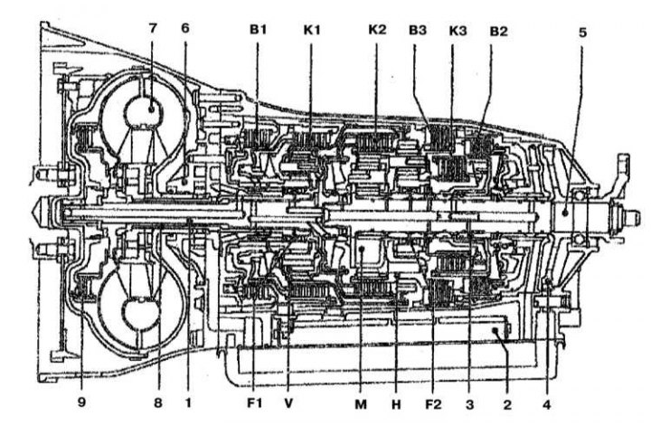
1 - Input shaft; 2 - ECU; 3 - Intermediate shaft; 4 - Parking lock gear; 5 - Output shaft; 6 - Oil pump; 7 - Torque converter; 8 - Reactor shaft; 9 - Locking clutch of the torque converter; B1 - Multi-disc brake assembly B1; B2 - Multi-disc brake assembly B2; B3 - Multi-disc brake assembly B3; F1 - Flywheel F1; F2 - Flywheel F2; H - Rear planetary assembly; K1 - Multi-disc clutch K1; K2 - Multi-disc clutch K2; K3 - Multi-disc clutch K3; M - Central planetary assembly; V - Front planetary assembly
Scheme of transmission of rotation in position «1» AT selector
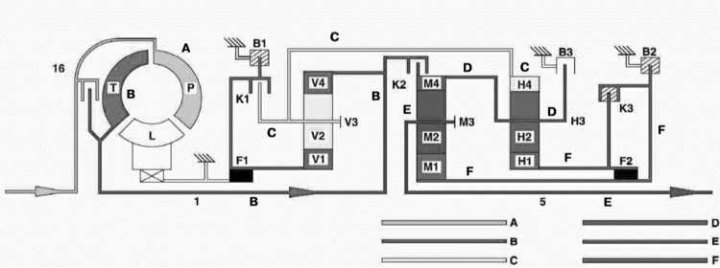
1 - Input shaft; 2 - Output shaft; 16 - Locking clutch of the torque converter; A - The speed of rotation of the crankshaft; B - Transmission, input rotation speed; C - 1st gear ratio; D - 2nd gear ratio; E - 3rd gear ratio; F - Fixed parts; H - Rear planetary gear set; L - Stator; M - Central planetary gear set; P - Impeller; T - Turbine wheel; V - Front planetary gear set
Automatic transmission control unit
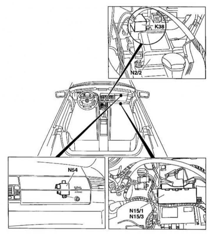
K38 - Starter blocking relay module; N2/2 - SRS control module; N15/1 - 5-speed AT control module (TCM); N15/3 - Transmission control module (TCM); N54 - RCL control module
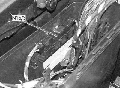
Location of the automatic transmission control module
Automatic transmission, in the process of starting off, performs the function of an ordinary clutch, and while driving, it performs the work of shifting gears.
The main units of the AT are: a torque converter, a planetary gearbox and a hydraulic or electronic control system. To switch to another gear ratio in the planetary gearbox, hydraulic disc brakes and a disc clutch are used.
The torque converter has the same function as a hydraulic clutch. Its task is to carry out the clutch when starting off and shifting gears.
The principles and schemes for the construction and operation of AT are discussed in detail in the manual «Automatic transmissions of modern cars» ARUS publishing house.
transmission control system (known as electronic synchronous shifting system) is an integral part of the modified engine management system. The control system can operate in a special safe mode, which it switches to when any malfunction is detected. In this case, the transmission modes are limited, and the car can be delivered under its own power to the repair shop. When the control system enters the safe mode, the control lamp lights up on the dashboard (contact the head Manual). Analyzing information coming from various sensors (not only sensors directly related to the transmission), the control system selects the optimal one in terms of economy, smoothness, etc. box mode. At a certain throttle position, the control system can lock up the torque converter so that only fourth and fifth gears are engaged. This achieves a significant reduction in fuel consumption.
The only regular maintenance procedure for the box is to check the fluid level (refer to section Checking the automatic transmission oil level). It is not necessary to change the transmission fluid regularly.
A transmission fluid cooler is installed next to the radiator of the cooling system.
There is no traditional kick-down switch. The inclusion of this mode is carried out directly by the transmission control system after processing information from the throttle position sensor.
There are several modes of operation of the transmission, each of which can be engaged after moving the selector to one of the following positions: P, R, N, D, 1, 2, 3, 4 (contact the head Manual).
The engine can only be started if the selector is in position P or N. This is done in order to prevent the car from moving when trying to start (if the selector is set to one of the other positions). Analyzing the information coming from the sensors, the control system allows or prohibits the engine start. The locations of the various relays are indicated in Chapter Onboard electrical equipment.