
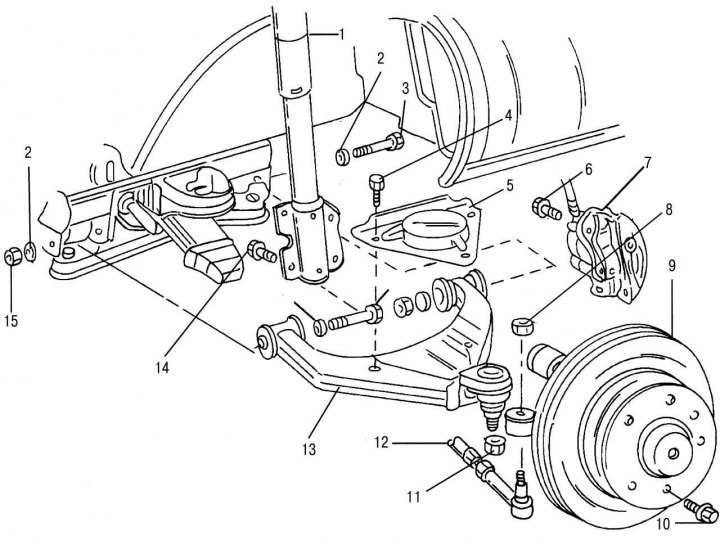
Pic. 206. Removal and installation of the transverse suspension arm: 1 - shock absorber strut; 2 - washer; 3 - hex bolt, M14x1.5; 4 - hex bolt, M10, 40–50 Nm; 5 - triangular plate; 6 - brake caliper mounting bolt, M14x1.5, 175–205 Nm; 7 - brake caliper; 8 - hex washer, M16x1.5, 120–130 Nm; 9 - knuckle with hub and brake disc; 10 - wheel bolt, 160–180 Nm; 11 - hex nut, M20x1.5, 280–300 Nm; 12 - steering rod; 13 - transverse lever; 14 - hex bolt, M14x1.5, 300–320 Nm; 15 - hex nut, 130-150 Nm
Fastening of the lower triangular suspension arm is shown in fig. 206. The lever can be removed without dismantling the bridge. If the bridge has already been removed, as described above, work must be carried out according to the recommendations below.
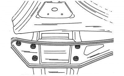
For removal and installation, it is necessary to make a fixture from hardwood, plastic or metal measuring 100x20x40 mm.
You will also need a torque wrench with a large tightening torque limit, a puller for tie rod pins and ball joint pins. Removal of the lower transverse suspension arm must be carried out as follows:
Pic. 207. Transverse arm removal tool
- install the device indicated above between the spring and its support, as shown in fig. 207;
- loosen the wheel bolts, jack up the front of the car and put it on stands. Remove wheels;
- remove the brake caliper and attach to the front axle. Do not leave the caliper hanging on the brake hose;
- unscrew the nut of the tie rod lever pin and press out the steering lever pin with a puller;
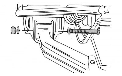
- place the rolling jack under the transverse arm and raise it by 10 mm to unload from the force of the spring;
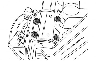
Pic. 208. Mounting the shock absorber strut from below
- unscrew the four bolts of the shock absorber strut (pic. 208) and slowly lower the lever on the jack;
- from the lower side of the transverse lever, unscrew the nut of the ball joint pin and, using a puller, remove the ball pin from the lever;
- unscrew the triangular plate fixed on three bolts from above. If an anti-roll bar is installed, pull the plate up and leave it on the stabilizer. In the usual case, just remove it;
Pic. 209. Fastening of a forward bar of the cross-section lever
- unscrew the nut of the lever support pin from the rear side and remove the washer. Knock out a finger. In the same way, unscrew and knock out the pin on the other side of the lever fork. The lever attachment is shown in fig. 209. Be careful: after knocking out both fingers, the lever may fall.