
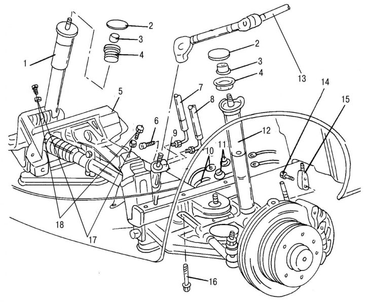
Pic. 198. Front axle assembly: 1 - shock absorber strut right; 2 - cover; 3 - rack mounting nut, 90–110 Nm; 4 — the top rubber support of a rack; 5 - front axle; 6 - bolt (with internal hexagon) steering joint mounts, 30-35 Nm; 7 — a hose of the amplifier of a steering; 8 — a hose of a return contour of the amplifier of a steering; 9 — rack and pinion steering mechanism; 10 — a hose of brake system; 11 - tee of pipelines of the brake system; 12 - shock absorber strut left; 13 - intermediate steering shaft with a hinge; 14 — a bolt of fastening of a wire of the sensor of wear of brake pads; 15 - brake pad wear sensor wire; 16 - connecting bolt for fastening the bridge to the cross beam, 90–100 Nm; 17 — washers of bolts of fastening of the engine; 18 - engine mounting bolts, 80–90 Nm
The removal of the front axle assembly is described below. This is only necessary if the vehicle has been in an accident. Many parts of the bridge can be removed without dismantling the entire assembly. On fig. 198 shows the shock absorber mount. When disassembling, it should be borne in mind that the front axle is quite heavy, so the jack or other lifting devices used must have an appropriate load capacity.