
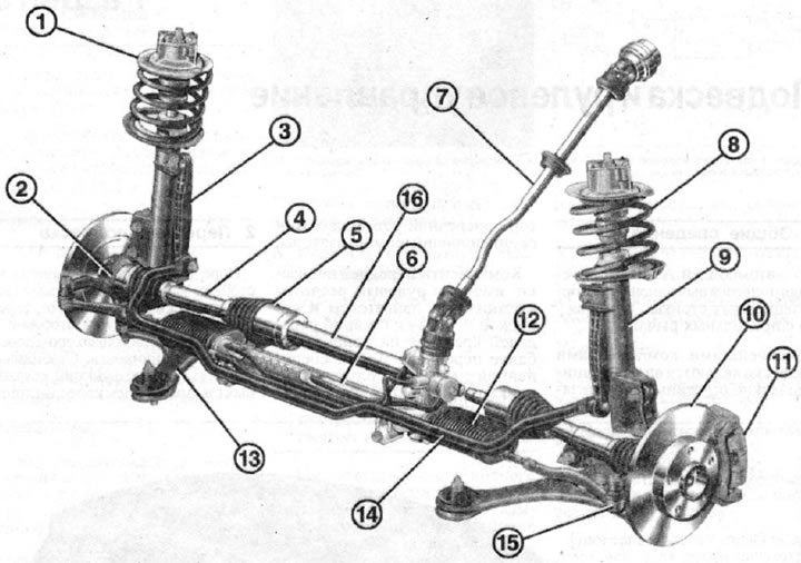
2.0 Front suspension
1 - suspension strut, which is a shock absorber with a coiled coil spring
2 - steering knuckle
3 - connecting rack of the anti-roll bar on the shock absorber
4 - half shaft
5 - internal hinge (SHRUS)
6 - rack and pinion steering gear
7 - steering column
8 - twisted spring shock absorber
9 - telescopic shock absorber
10 - brake disc
11 - brake caliper
12 - cuff of the steering mechanism
13 - independent suspension wishbone
14 - torsion stabilizer bar
15 - tie rod end
16 - intermediate drive shaft
The front suspension is made on MacPherson struts with coil springs, telescopic shock absorbers and a torsion bar anti-roll bar. The stabilizer does not perform functions related to the direction of the wheels, it is only connected by the corresponding struts to the shock absorbers. The function of guiding the wheels is performed by two triangular independent suspension arms. Suspension components, together with the steering rack, engine and transmission, are mounted on the front axle cross member connected to the body (see illustration 2.0).
Optimum driving performance and minimal tire wear are ensured by perfect wheel alignment. If the tires show abnormal wear or their camber and toe-in are not set correctly, you should immediately contact a workshop to correct the camber and toe. Wheel alignment angles cannot be set independently, without a special device. The angle of the axis of the front wheels in A-class vehicles is 0°29'±10'.
The engine torque is transmitted to the front wheels by means of two semi-axes, each of which has two hinges of equal angular velocities. The front axle does not require maintenance.
Attention! Welding and straightening work on the bearing and guiding elements of the front suspension is prohibited. Always replace self-locking nuts and rusted bolts and nuts with new ones when carrying out repairs.