
Cars BMW Cars Volkswagen Cars Chevrolet Cars Land Rover Cars Lada Cars Honda Cars Peugeot
English Русский
Български
Беларускі
Український
Српски
Hrvatski
Română
Polski
Slovenský
Magyar
Bookmark News and articles Sitemap Feedback Site search
MercedesMan.ru


A-Class C-Class E-Class G-Class M-Class S-Class Others
Sprinter (1995-2000, diesel) Vito 1 (1996-2003) Vito 2 (2003-2014, diesel) Vario 814D (1996-2003, diesel)
  • Main
  • Mercedes-Benz
  • Sprinter (1995-2000)
  • Transmission
  • Front axle
  • Removal the front axle

Removal the front axle (Mercedes-Benz Sprinter 903)

0
If your vehicle is not equipped with an ABS system, you can skip the description regarding the steering knuckle speed sensor. Removal of the front axle must be carried out in the following order:

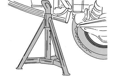
Figure 199. Place of installation of special supports

Figure 199. Place of installation of special supports

  • loosen the wheel mounting bolts before lifting it with a jack, place the front of the car on supports. To have access to all parts, the supports should be installed on the right and left in the places shown in the figure 199. Remove both front wheels;
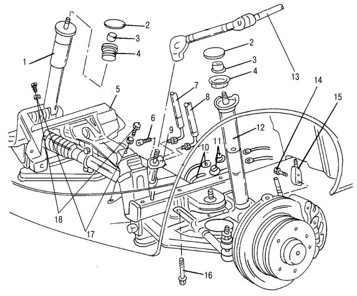
Figure 198. Front axle assembly: 1 — shock absorber strut right; 2 - lid; 3 — rack mounting nut,…

Figure 198. Front axle assembly: 1 — shock absorber strut right; 2 - lid; 3 — rack mounting nut, 90–110 N·m; 4 - Upper rubber support of the rack; 5 - front axle; 6 — bolt (with internal hexagon) steering joint mounts, 30–35 Nm; 7 — power steering hose; 8 — power steering return line hose; 9 - rack and pinion steering mechanism; 10 — brake system hose; 11 — tee of brake system pipelines; 12 — shock absorber strut left; 13 — intermediate steering shaft with joint; 14 — bolt for fastening the brake pad wear sensor wire; 15 — brake pad wear sensor wire; 16 — connecting bolt for fastening the bridge to the cross beam, 90–100 N·m; 17 — engine mounting bolt washers; 18 — engine mounting bolts, 80–90 Nm
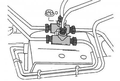


Figure 200. Brake pipe tees

Figure 200. Brake pipe tees

  • unscrew the union nuts of the hoses 10 (figure 198) brake system from both tees 11 and remove the hoses (figure 200). To avoid confusion in the order of connecting the hoses to the tees, make appropriate marks before removing them. Remove both tees. Close the hose openings with plugs to prevent dirt from getting in;
  • unscrew bolt 14 securing wire 15 of the brake pad wear sensor and disconnect the sensor wire connector;
  • in a car with ABS system disconnect the speed sensor wire in the steering knuckle. The sensor can also be removed without disconnecting the wires. In this case, unscrew the mounting bolt and remove the sensor;
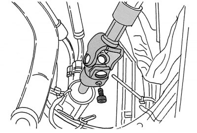
Figure 201. Intermediate steering shaft with hinge

Figure 201. Intermediate steering shaft with hinge


  • use a hex key to unscrew the locking bolt 6 from the steering joint and disconnect the joint 5 together with the intermediate shaft from the rack and pinion gear 12. Figure 201 shows this connection;
  • use special clamps to pinch hoses 7 and 8 of the power steering to prevent fluid from leaking out of the system and unscrew the union nuts of the hoses from the mount. A little liquid will leak out and need to be collected. Wrap the ends of the hoses with adhesive tape to protect them from dirt;
  • from inside the cabin, loosen the nuts 3 securing the shock absorber struts, having first removed the protective covers 2. On the left side, the cover is located in the driver's footwell;
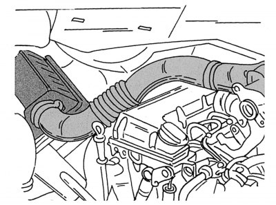
Figure 202. Air duct

Figure 202. Air duct

  • remove the air duct. Figure 202 shows its attachment to the air filter and engine;
  • use a hand crane or winch to lift the engine until its supports are unloaded. The cables should be secured in special lifting eyes;
  • place a jack under the front axle, but do not lift it;
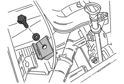
Figure 203. Fastening the engine support on the left side

Figure 203. Fastening the engine support on the left side


  • unscrew the engine mount on the left and right sides (bolt 18 and washer 17, shown in the figure 198) Figure 203 shows the support on the left side (next to the oil dipstick). On the right side the support looks the same. Before loosening the engine mount, make sure once again that the engine is securely suspended;
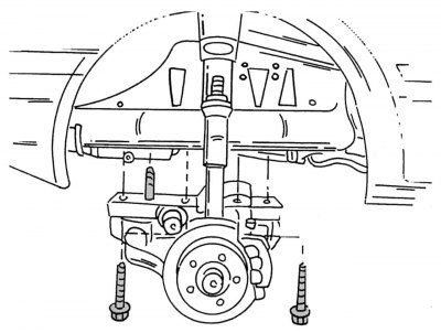
Figure 204. Removing the front axle

Figure 204. Removing the front axle

  • disconnect the front axle on the right and left sides from the side members by unscrewing the mounting bolts. Figure 204 shows where bolts 16 are installed (see figure 198);
  • slowly lower the bridge onto the jack provided. The assistant should hold the bridge on one side. It is better if two assistants hold the bridge on both sides. Do not hold the axle by the brake disc covers as they may bend.
This article is available at: russian, bulgarian, belarusian, ukrainian, serbian, croatian, romanian, polish, slovak, hungarian
The article has been verified: Levin Kirill Glebovich
Share with friends:
◀ Previous
Mercedes Sprinter / Front axle
Next ▶

Front axle design
General description of the front axle
Installing the front axle
Removal the lower control arm
Installing the transverse arm
Replacing the ball joint
Replacing the silent blocks of the transverse levers
More similar articles for repairing other models

☛ Front axle beam — removal and installation Mercedes W168 (1997-2004)
☛ Front axle / steering Mercedes W202 (1993-2000)
☛ Diagram 2. Front axle speed signal (GES) (engines 104, 111, 602, 604,… Mercedes W210 (1996-2002)
☛ Checking the grease packing of the pivot housings of the front axle… Mercedes W463 (1999-2019)
☛ Removal and installation the front axle assembly Mercedes W163 (1997-2005)
☛ Removal and installation the upper front covers Mercedes W140 (1991-1998)
Link in different formats to this article
Comments and feedback from visitors
No comments yet


How much will 22 + 17 ?


Vario 814D (1996-2003, diesel) 
  • General information
  • Maintenance
  • Power unit
  • Engines 602.984/985
  • Engines 904.908/914/923/936
  • Transmission
  • Clutch
  • Manual gearbox 711.613
  • Manual gearbox 710.64/66
  • Manual gearbox 715.051
  • Automatic gearbox 723.345
  • Power take-off box
  • Chassis
  • Front suspension
  • Rear suspension
  • Steering
  • Brake system
  • Body and electrical equipment
  • Interior (internal elements)
  • Exterior (external elements)
  • Heater and air conditioner
  • Electrical diagrams
Vito 2 (2003-2014, diesel) 
  • General information
  • User manual
  • Maintenance
  • Diesel engine OM646
  • Engine repair
  • Cooling and lubrication system
  • Power and exhaust system
  • Transmission
  • Clutch
  • Car gearbox
  • Chassis
  • Front suspension
  • Rear suspension
  • Steering
  • Brake system
  • Body
  • Body elements
  • Electrical equipment
  • Equipment and devices
  • Security systems
  • Electrical circuits
Vito 1 (1996-2003) 
  • General information
  • User manual
  • Maintenance
  • Petrol engines 2.0 l
  • Engine repair
  • Lubrication system
  • Cooling system
  • Power and control system
  • Petrol engines 2.8 l
  • Engine repair
  • Lubrication system
  • Cooling system
  • Power and control system
  • Diesel engines 2.3 l
  • Engine repair
  • Cooling system
  • Lubrication system
  • Turbocharging and recycling
  • Power and control system
  • Diesel engines 2.2 l
  • Engine repair
  • Cooling system
  • Lubrication system
  • Turbocharging and recycling
  • Power and control system
  • Transmission
  • Clutch
  • Mechanical gearbox
  • Automatic gearbox
  • Chassis
  • Front suspension and wheels
  • Rear suspension
  • Steering
  • Brake system
  • Body
  • Exterior (external elements)
  • Interior (internal elements)
  • Electrical equipment
  • Equipment and devices
  • Heater and air conditioner
  • Electrical circuits
Sprinter (1995-2000, diesel) 
  • General information
  • Introduction to the guide
  • Maintenance
  • Power unit
  • Engine repair
  • Lubrication system
  • Cooling system
  • Power and exhaust system
  • Transmission
  • Clutch
  • Mechanical gearbox
  • Automatic gearbox
  • Front axle
  • Rear axle and cardan
  • Chassis
  • Car suspension
  • Steering
  • Brake system
  • Tires and wheels
  • Electrical equipment
  • Equipment and devices
  • Headlights and lighting
  • Power devices
  • Electrical circuits
 
MercedesMan.ru © 2017–2026 · Mobile version · Read about Mercedes · Sitemap: EN BG BY UA RS HR RO PL SK HU · Feedback · Site search · Bookmark A-Class (W168) · C-Class (W201) · C-Class (W202) · C-Class (W203) · E-Class (W123) · E-Class (W124) · E-Class (W210) · G-Class (W463) · M-Class (W163) · S-Class (W116, petrol) · S-Class (W126, petrol) · S-Class (W140) · S-Class (W220) · Sprinter · Vito 1 · Vito 2 · Vario 814D ·
 
We only use cookies without which some of the site's features may not be available.