
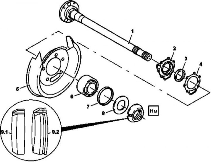
Rear axle design
1 - Half shaft; 2 - Bearing cover; 3 - Oil seal; 4 - Gasket; 5 - Brake shield; 6 - Tapered roller bearing; 7 - O-ring of rectangular section; 8 - Locking plate; 9.1 - Slotted nut with right-hand thread; 9.2 - Slotted nut with left-hand thread
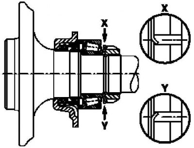
Shaft rotation direction (arrows)
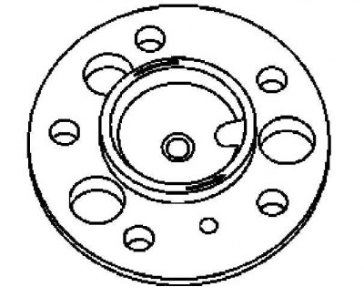
Blocking slotted nuts on the example of the left half shaft
1. Remove the half shaft (see Section Removal and installation of semiaxes).
2. Screw into the hub flange of the axle shaft (1) a couple of wheel bolts and clamp them in a vise.
3. Unlock and unscrew slotted nuts (9).
4. Remove the lock plate (8).
5. Using special mandrels and a press, dismantle from the axle shaft (1) tapered roller bearing (6), - take care not to damage the ABS wheel sensor rotor.
6. Remove gasket (4), cover (2) with stuffing box (3) and brake pad (5).
7. Remove from cover (2) stuffing box (3) and put a new one in its place, lightly lubricating its sealing lips - make sure that the depth of the stuffing box in the seat of the cover is no more than 0.3 mm.
8. Plant cover (2) on the half shaft (1), then install the brake shield (5), by filling the space between the shield and the stuffing box lips with grease (3).
9. Land on the half shaft (1) bearing (6), by tightening it with a NEW locking plate (8).
Attention! lock plate (8) is installed with the flat side to the slotted nut and must only rest against the inner race of the bearing! The anti-rotation lock of the circlip must align with the machined section of the axle shaft to prevent damage to the latter. Make sure that the outer race of the bearing rotates during the pressing process!
10. Install slotted nut (9).
11. Block both slots of the slotted nut (9) lock plate (8), - the nut must not be released when the axle shaft is rotated in any direction.
12. Place on bearing (6) rectangular O-ring (7).
13. Reinstall the half shaft (see Section Removal and installation of semiaxes).