
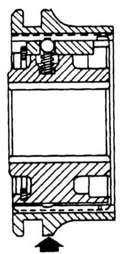
Output shaft parts
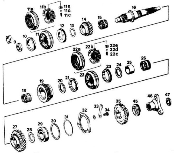
9 - front nut with a longitudinal slot (or hex); 10 - blocking ring synchronizer IV gear; 11 - synchronizer with a sliding ring for III and IV gears; 11a - synchronizer clutch of III and IV gears; 11b - synchronizer hub; 11c - synchronizer pressure springs; 11d - steel ball; 11e - cracker; 12 - a blocking ring of the synchronizer of the III transfer; 13 - thrust washer III gear; 14 - third gear gear; 15 - needle bearing III gear; 16 - secondary shaft; 18 - needle bearing II gear; 19 - gear wheel of the 2nd gear; 20 - thrust washer; 21 - a blocking ring of the synchronizer of the II transfer; 22 - synchronizer of I and II gears with a sliding clutch; 22a - sliding clutch of the synchronizer of I and II gears; 22b - synchronizer hub of I and II gears; 22c - synchronizer pressure spring; 22d - steel ball; 22e - synchronizer cracker; 23 - blocking ring of the synchronizer of the 1st gear; 24 - thrust washer; 25 - bearing cage of the 1st gear; 26 - needle bearing of the 1st gear; 27 - gear wheel of the 1st gear; 28 - thrust washer; 29 - deep groove ball bearing; 30 - retaining ring; 31 - compensation washer; 32 - retaining ring of the rear bearing of the secondary shaft; 33 - locking plate; 34 - bolt; 35 - reverse gear gear; 45 - speedometer gear; 46 - output shaft flange; 47 - locknut
Disassembly
1. Install the drive flange on the rear end of the output shaft (temporarily) and secure it vertically in a vise.
2. Turn away a nut from the forward end and remove the synchronizer of III and IV transfers and a blocking ring.
3. Remove the 3rd gear thrust washer, 3rd gear gear and needle bearing.
4. Release the shaft from the vise and remove the thrust washer, 1st gear gear and needle bearing rollers from the rear end.
5. Place the driven shaft in a vice so that the 2nd gear gear is at the bottom, and with a soft metal hammer, lower it down so that the inner race of the 1st gear needle bearing is released.
6. Release the output shaft from the vise and remove the inner ring, thrust washer (if it exists), the 1st gear synchronizer blocking ring, the 1st and 2nd gear synchronizer and the 2nd gear synchronizer blocking ring.
7. Remove thrust washer (if it exists), 2nd gear gear and needle bearing.
8. Wash all parts in solvent (kerosene) and carry out a troubleshooting. Notice the spiral (roundabouts) springs and balls.
9. Put each synchronizer ring on its conical seat in the gear and use a feeler gauge to measure between the gear teeth less than 0.5 mm, replace the synchronizer ring.
10. Disassemble the synchronizer. When disassembling a synchronizer with coil springs, wrap it in cloth, mark the position of the hub relative to the clutch, and then pull the hub out of the clutch. As soon as the hub comes out, the crackers, balls and springs will be displaced (spring guides are provided on the V gear synchronizer). Replace worn parts and assemble the synchronizer by placing the springs and keys in the hub. Then, keeping the keys pressed, partially insert the hub into the coupling. Place the balls one by one into the hub and when all three are installed, push the entire hub into the coupling. Please note that the synchronizing rings of I and II gears have a bevel at one corner. When installing, check that the bevel is facing the 2nd gear gear.
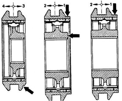
Synchronizer with ring springs
V gear synchronizer with ring springs
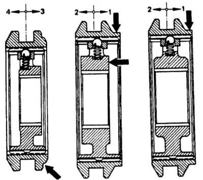
Synchronizer with coil springs
V gear synchronizer with coil springs
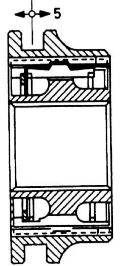
Checking the degree of wear of the synchronizer blocking ring using a feeler gauge
Synchronizer disassembly
1. In order to disassemble the synchronizer with ring springs, note the position of the hub relative to the clutch, then remove the spring ring (only for V gear synchronizer), push the hub out of the clutch and pull out the crackers and springs. Replace worn parts with new ones and assemble the synchronizer again, restoring the position of the hub relative to the clutch.
2. Note that the angled ends of the springs must be in the same pocket, and that the springs must face in opposite directions.
Assembly
1. Install the intermediate shaft vertically in a vice with soft (aluminum) sponges so that its back end looks up. As parts are installed, lubricate them with clean gear grease.
2. Install the 2nd gear needle bearing onto the 2nd gear and thrust washer (if provided).
3. Install the 2nd gear synchronizing ring on the 2nd gear gear and press the 1st and 2nd gear synchronizer assembly onto the splines.
4. Install the synchronizer ring of the 1st gear on the synchronizer, put the thrust washer (if provided).
5. Heat the inner race of the 1st gear needle bearing and quickly press it into place on the output shaft with a drift.
6. Install the needle rollers, 1st gear gear and thrust washer. Lock the 1st gear gear and needle bearing in place with a piece of tube and a flange nut.
7. Turn the shaft over in a vise (back end looking down) and secure it. Install 3rd gear needle bearing and toothed thrust washer (if provided).
8. Install the 3rd gear synchronizer ring onto the 3rd gear gear and press the 3rd and 4th gear synchronizer assembly onto the splines with the splined side of the coupling forward.
9. Screw the nut onto the front end of the driven shaft and tighten it to a torque of 8.0 kgf·m, fix the nut into the groove of the shaft.