



Disassembly into basic units
1. Clean the outside of the gearbox with kerosene and dry it.
2. Remove the clutch components (lever, release bearing, clutch housing).
3. Drain the oil through the drain plug hole and install it back.
4. Remove the reverse gear and 5th gear lever, having first marked its position relative to the shaft.
5. Remove the snap ring and washer from the shaft.
6. Loosen the mounting bolts and remove the gearshift mechanism mounting cover, having first removed the levers.
7. Unscrew the bolts securing the front cover to the gearbox housing, noting the position of the bearing axial play adjustment gaskets.
8. Lock the output shaft flange and unscrew the special nut with a crown wrench.
9. Using a puller, remove the drive flange.
10. Disconnect the rear cover mounting bolts and remove it.
11. Remove the speedometer drive worm gear from the driven shaft.
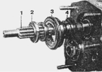
Removing the primary shaft from the gearbox housing
1 — primary shaft
2 - Nut with longitudinal slot
3 - bearing
4 - oil deflector
Four-speed gearbox
1. Remove the reverse gear from the intermediate shaft.
2. Remove the reverse intermediate shaft and disconnect the intermediate gear from the gear selection fork.
3. Remove the nut from the rear end of the intermediate shaft and remove the reverse gear.
Note: To facilitate disassembly, temporarily reinstall the driven shaft flange, install the locking rod and engage top gear (IV or V).
4. With the transmission in neutral, remove the gear shift forks from the synchronizer sliding sleeves.
5. Using a punch, remove the cylindrical pin from the reverse gear fork retainer and remove the switch shaft.
6. Bend back the lock washers, unscrew the lock plate mounting bolts and unscrew the nut from the front end of the secondary shaft.
7. Using a puller, remove the support bearing mounting plates and take out the intermediate shaft bearings.
8. Remove the front and rear bearings of the driven shaft in the same way.
9. Install a metal tube on the rear end of the intermediate shaft to ensure that the 1st gear is locked in the needle bearing.
10. Lift the rear end of the secondary shaft and remove the primary shaft through the front of the crankcase.
11. Remove the primary shaft, 4th gear synchronizer ring and needle bearing.
12. Move the synchronizer clutch of III and IV gears to the III gear position.
13. Move the intermediate shaft back and remove it through the side window of the crankcase.
14. Move the secondary shaft back and remove it through the side window of the crankcase.
[Read more on the website: Mercedesman.ru]
Five-speed gearbox
1. Remove the gear shift forks from the synchronizer grooves.
2. Unscrew the nut from the rear end of the driven shaft. To prevent the driven shaft from rotating, temporarily move the synchronizer clutches to engage two gears at once.
3. Unscrew the intermediate case mounting bolts and remove it together with the bearings. In case of a tight fit, you can leave the bearing on the intermediate shaft.
4. Use a puller to remove the 5th gear from the intermediate shaft.
5. Unscrew the bolts securing the intermediate crankcase to the main crankcase and remove the gasket.
6. Use a punch to knock out the cylindrical pin from the gear shift lock, reverse/5th gear and move the pawl to the extreme forward position.
7. Pull out the reverse/V gear stop mandrel with the spring and the stop ball through the side window.
8. Disconnect the intermediate shaft from the reverse gear, releasing the latter from the engagement fork.
9. Remove the intermediate shaft together with the 5th gear, needle bearing and synchronizer ring.
10. Using a puller, remove the reverse gear, 5th gear synchronizer and 5th gear needle bearing ring.
11. Remove the reverse/V gear engagement fork from the crankcase.
12. Remove the parallel key from the intermediate shaft and remove the gasket and reverse gear from the splines.
13. Inspect the gasket installed between the synchronizer and the reverse gear for defects.
14. Remove both secondary shaft woodruff keys.
15. Loosen the bearing nut of the front end of the secondary shaft, using the simultaneous engagement of two gears to secure the shaft.
16. Remove the bearing cover from the rear of the crankcase and take out the axial float adjustment shims.
17. Remove the inner snap ring and the drive shaft bearing. Remove the crankcase bearing and the oil sprayer.
18. Remove the secondary shaft rear bearing.
19. Secure the 1st gear pinion with a metal mandrel to prevent it from shifting out of the needle bearing.
20. Remove the ball bearing (if he stayed) from the crankcase or remove from the front of the secondary shaft. If a roller bearing is installed, you will need to use a soft-faced hammer to drive the secondary shaft back in with the roller bearing and tapered bushing (if there is one). At the same time, the assistant lifts the primary and intermediate shafts.
21. Remove the primary shaft and bearing, the 4th gear synchronizer ring and the needle bearing. The intermediate shaft is located at the bottom of the crankcase.
22. Move the synchronizer clutch of III and IV gears to the III gear position and, having moved the intermediate shaft back, remove it through the side window of the crankcase.
23. Move the secondary shaft back and remove it through the side window of the crankcase.