
Driven shaft manual transmission according to No. 0210417
Disassembly
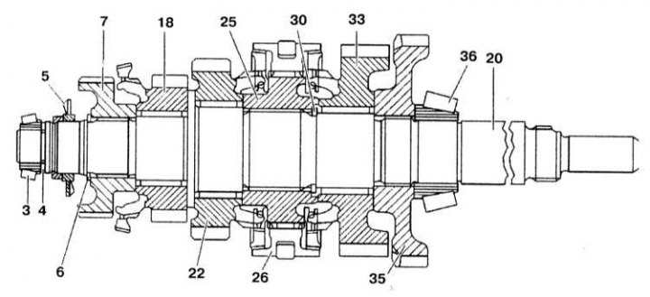
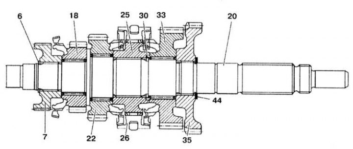
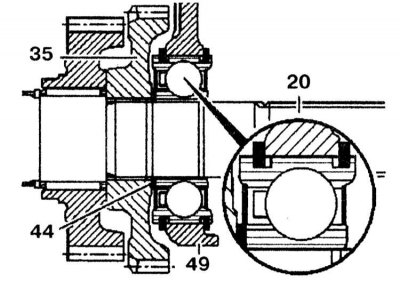
The design of the driven shaft of the manual transmission up to No. 0210417
3, 36 - Tapered roller bearings; 4 - Gasket; 5 - Impeller; 6, 30 - Retaining rings; 7 - Synchronizer 3/4th gear; 18 - Gear 3rd gear; 20 - Driven shaft; 22 - Gear 2nd gear; 25 - Synchronizer for engaging 1/2 gears; 26 - 1/2 gear engagement fork; 33 - Gear 1st gear; 35 - Reverse gear; 37 - 5th gear
1. Remove the tapered roller bearing (3).
2. Remove gaskets (4).
3. Press out the impeller (5) with a screwdriver.
4. Remove retaining ring (6).
5. Remove the 3rd/4th gear synchronizer (7) and 3rd gear (18) with needle bearing.
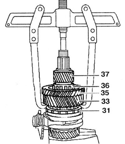
6. Press out the 1st gear, reverse gear and tapered roller bearing. To do this, install the puller on the 1st gear (33) and remove the gears (33) And (35) with tapered roller bearing (36).
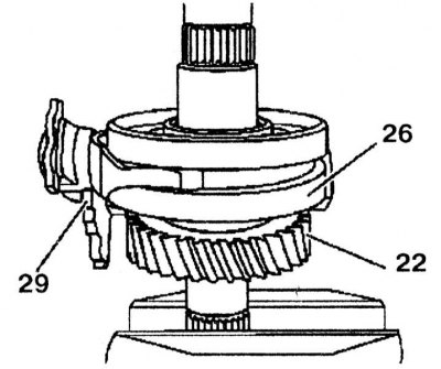
7. Remove the clutch, fork and shift lever. Remove the lever first (29) with shift fork. Remove the clutch (26) from the synchronizer.

8. Remove retaining ring (30).
9. Remove the synchronizer (25) 1/2 gear engagement and 2 gear gear (22) with needle bearing.
10. Remove the synchronizer rings.
11. Check all removed elements for wear.
12. Clamp the input shaft without synchronizer rings in a vice with soft jaws.
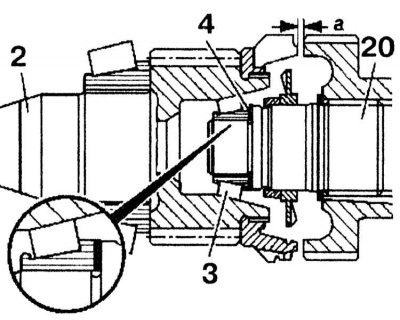
13. Install the output shaft onto the drive shaft. Rotate the driven shaft until the tapered bearing is seated correctly. 14. Measure the distance «a» between limiter and synchronizer (7) 3/4th gear.

15. Adjust the distance «a» gaskets (4), for which remove or press in the tapered roller bearing (3). Gaskets are available in thicknesses of 0.05, 0.1, 0.5, 0.9 and 1.2 mm.
16. Install the output shaft in the intermediate housing, rotate the output shaft so that the tapered bearing is installed in the correct way.
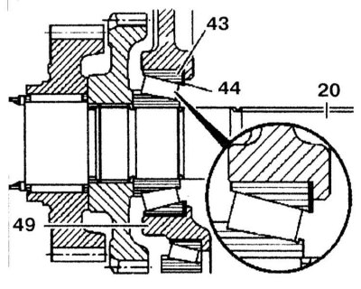
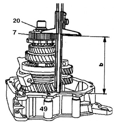
17. Measure the distance «b» between synchronizer (7) 3/4th gears and contact surface of the intermediate housing (49).

18. Remove the bearing outer race (43) intermediate crankcase (49), insert gaskets (44) and press in the bearing outer race again. Gaskets are available in thicknesses of 0.2, 0.3 and 0.5 mm.
Assembly
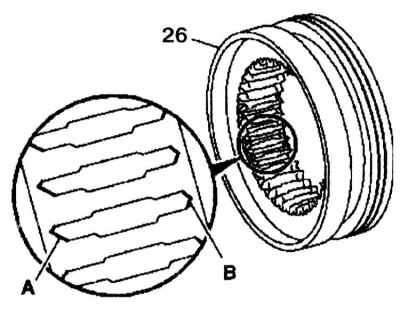
1. Assembly is carried out in the reverse order of removal. Install clutch (26) so that the asymmetrical tips of the slots (A) were installed towards the 2nd gear (22).
2. Install the lever fork (29). The distance between the input and output shafts should be 1.5 mm, the distance between the 3rd/4th gear synchronizer and the contact surface of the intermediate housing should be 138.4 mm.


Driven shaft for manual transmission from No. 0210418 to No. 6141000
Disassembly
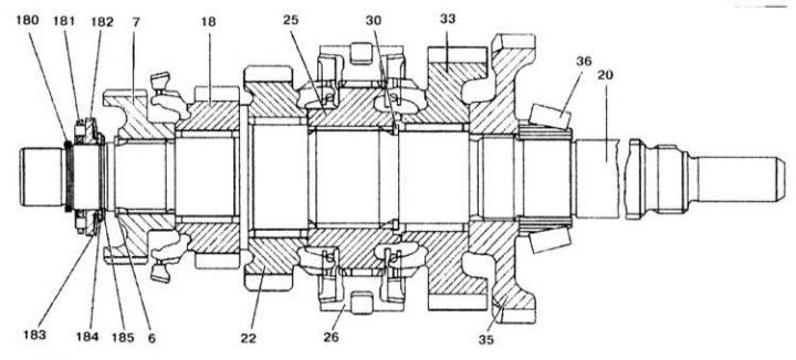
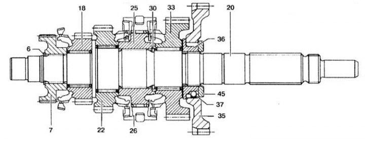
The design of the driven shaft of the manual transmission from No. 0210418 to No. 6141000
6, 30, 180, 185 - Retaining rings; 7 - Synchronizer 3/4th gear; 18 - Gear 3rd gear; 20 - Driven shaft; 22 - Gear 2nd gear; 23 - Synchronizer 1/2 gears; 26 - 1/2 gear engagement fork; 33 - Gear 1st gear; 35 - Reverse gear; 36 - Tapered roller bearing; 181 - Thrust bearing; 182 - Disc spring; 183 - Spring gasket; 184 - Gasket
1. Remove retaining ring (180), thrust bearing (181), disc spring (182),spring gasket (183), gaskets (184) and retaining ring (185).
2. Remove retaining ring (6). Retaining rings are available in 1.2, 1.3 and 1.4 mm thicknesses.
3. Remove the synchronizer (7) 3/4th gear t gear 3rd gear (18) with needle bearing.
4. Remove the 1st gear, reverse gear and tapered roller bearing.

5. Remove the fork with clutch and shift lever.

6. Remove retaining ring (30).
7. Remove the synchronizer (25) and 2nd gear (22) with needle bearing.
8. Remove the synchronizer rings.
9. Check all removed elements for wear and damage.
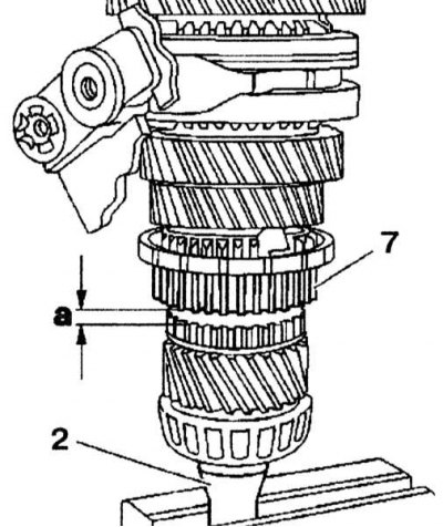
10. Clamp the drive shaft (2) without synchronizer rings in a vice with soft jaws.
11. Insert thrust washer (123), thrust bearing (124) and needle bearing (125) without spring (121).
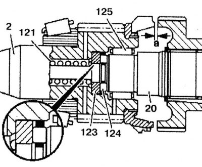
12. Measure the distance «a» between limiter and synchronizer (7) 3/4th gear. Adjust distance «a» with thrust washers (124). Thrust washers available (124) thickness from 4.3 to 5.2 mm in 0.1 mm increments.
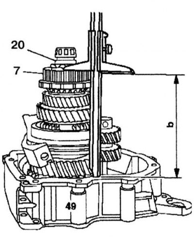
13. Measure the distance «b» between synchronizer (7) 3/4th gears and the contact surface of the intermediate housing (49).
14. Remove the bearing outer race (43) intermediate crankcase (49), insert gaskets (44) and press the outer race again (1) bearing. Gaskets are available in thicknesses of 0.2, 0.3 and 0.5 mm.

Assembly
1. Assembly is carried out in the reverse order of removal. Install clutch (26) so that the asymmetrical tips of the slots (A) were installed towards the 2nd gear (22).

2. Install the lever fork (29).
3. The distance between the drive and driven shafts is 1.5mm, the distance between the 3/4th gear synchronizer and the contact surface of the intermediate housing is 138.4mm.
Driven shaft for manual transmission from No. 6141001 to No. 6552834
Disassembly
The design of the driven shaft of the manual transmission from No. 6141001 to No. 6552834
8-3 - Shai6y; 6, 30 - Retaining rings; 7 - Synchronizer 3/4th gear; 18 - Gear 3rd gear; 20 - Driven shaft; 22 - Gear 2nd gear; 25 - Synchronizer 1/2 gears; 26 - 1/2 gear engagement fork; 33 - Gear 1st gear; 35 - Reverse gear; 44 - Gaskets
1. Remove retaining ring (6).
2. Remove the 3/4th gear synchronizer (7) and 3rd gear (18) with needle bearing (33).
3. Remove the reverse gear (55) with gaskets (44) and 1st gear.
4. Remove the fork with clutch and shift lever.

5. Remove retaining ring (30).
6. Remove the synchronizer (25) and 2nd gear (22) with needle bearing.
7. Remove the synchronizer rings.
8. Check all removed elements for damage and wear.
9. Press in the driven shaft (20) into the intermediate crankcase. Using a caliper, measure the distance «b» from synchronizer (7) 3/4th gear to the contact surface of the intermediate housing (49).

10. Remove the driven shaft (20) from intermediate crankcase (49), using a puller and install the gaskets (44) on the driven shaft (20). Gaskets are available in thicknesses of 0.2, 0.3 and 0.5 mm.

Assembly
1. Assembly is carried out in the reverse order of removal. Install clutch (26) so that the asymmetrical tips of the slots (A) were installed towards the 2nd gear (22).

2. Install the lever fork (29). The distance between the 3/4th gear synchronizer and the contact surface of the intermediate housing is 138.4 mm.

Driven shaft for manual transmission from No. 6552835 to No. 7011675
Disassembly
The design of the driven shaft of the manual transmission from No. 6552835 to No. 7011675
6, 30 - Retaining rings; 7 - Synchronizer 3/4th gear; 10 - Gear 3rd gear; 20 - Driven shaft; 22 - Gear 2nd gear; 25 - Synchronizer 1/2 gears; 26 - 1/2 gear engagement fork; 33 - Gear 1st gear; 35 - Reverse gear; 36 - Hub; 37 - Spring; 45 - Gaskets
1. Remove retaining ring (6).
2. Remove the 3/4th gear synchronizer (7) and 3rd gear (18) with needle bearing.
3. Remove the rear code transmission gear (35) with gaskets (45) and a hub.
4. Remove the 1st gear (33).
5. Remove the fork with clutch and shift lever.

6. Remove retaining ring (30).
7. Remove the synchronizer (25) and 2nd gear (22) with needle bearing.
8. Remove the synchronizer rings.
9. Check all removed elements for damage and wear.
10. Press in the driven shaft (20) into the intermediate housing. Using a vernier caliper, measure the distance «b» from synchronizer (7) 3/4th gear to the contact surface of the intermediate housing (49).
11. Using a puller, remove the driven shaft (20) from intermediate crankcase (49), and put gaskets on it (44). Gaskets are available in thicknesses of 4.3, 4.5, 4.7 and 4.9 mm.
Assembly
1. Assembly is carried out in the reverse order of removal. Install clutch (26) so that the asymmetrical tips of the slots (A) were installed towards the 2nd gear (22)
2. Install the lever fork (29). The distance between the 3/4th synchronizer and the contact surface of the intermediate case is 138.4 mm.
