
Removing
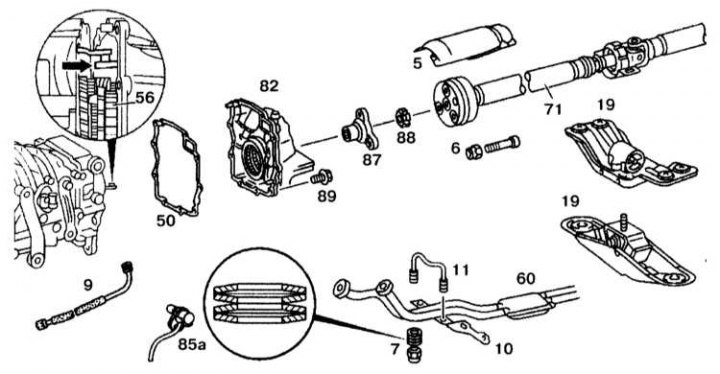
Details of installation of a back cover of a transmission
5 - Heat shield; 6, 7, 88 - Nuts; 9 - Speedometer shaft; 10 - Bracket for fastening the exhaust pipe; 11 - Bracket; 19 - Engine support; 50 - Gasket; 56 - Synchronizer clutch; 60 - Exhaust system; 67 - Flange; 71 - Front driveshaft; 82 - Rear cover of the gearbox; 85a - Inductive sensor; 89 - Bolt
1. Unscrew the engine mount (19).
2. Unscrew the bracket (10) exhaust system mounts and bracket (11).
3. Unscrew the heat shield (5).
4. Unscrew the front propeller shaft (71).
5. Disconnect the exhaust system (60) from the back sprinkling point.
6. Unscrew the speedometer shaft (9) or inductive sensor (85a).
7. Loosen the nut (88).
8. Remove the flange (87).
9. Disconnect the rear cover of the gearbox (82).
Disassembly
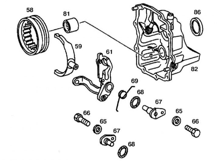
Dismantling and assembly of a back cover of a transmission
58 - Switching clutch; 59 - Shift fork; 61 - Lever; 65 - Gaskets; 66 - Bolts; 67 - Shaft; 08 - O-ring; 69 - Tension spring; 81 - Needle bearing; 82 - Rear cover of the gearbox; 86 - Radial oil seal
1. Remove the bolts (66) and remove the shaft (67).
2. Remove the lever (61), plug (59) and clutch (58). Remove coupling (58), plug (59) from the lever (61) and remove tension spring (69).
3. Remove the needle bearing (81) from the lid.
4. Press out the radial oil seal (86).
Assembly and installation
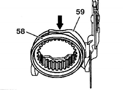
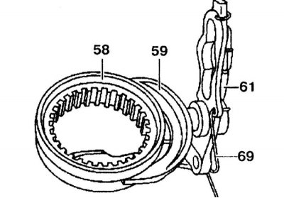
Install plug (59) on the clutch (58) so that the milled surface of the fork (59) was placed on top (arrow).
Assembly and installation are carried out in the reverse order of removal and disassembly. Install plug (59) on the clutch (58) so that the milled surface of the fork (59) was located on top.
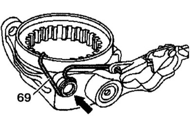
tension spring (69) must be installed on the cuff of the lever.
When installing, point the shift lever into the 5th gear and reverse gear fork (arrow). Turn the shifting sleeves and push them into the grooves of the synchronizer housing (56).