
Models with electronic VSS
Removing
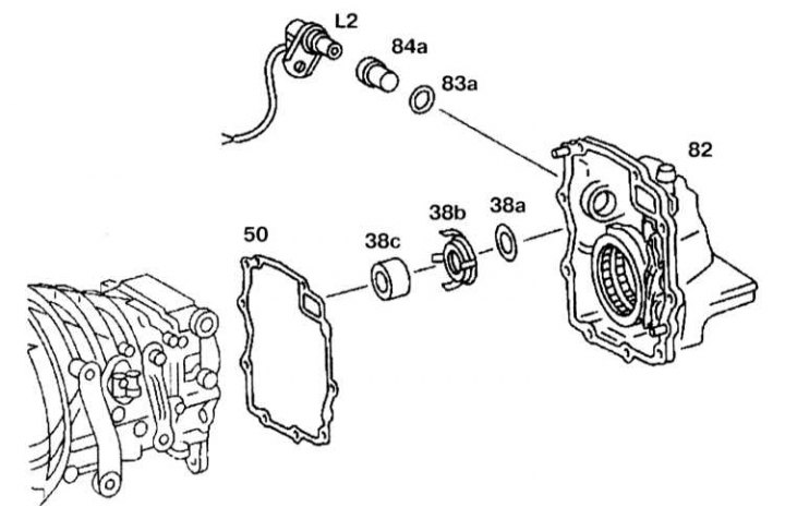
Electronic VSS Installation Details
38a - Thrust washer; 38b - Rotor; 38c - Hub; 50 - Sealing gasket; 82 - Rear cover of the gearbox; 83a - O-ring; 84b - Cover; L2 - Electronic vehicle speed sensor
1 Unscrew the sensor (L2).
2 Remove the cover (84a) sensor (L2).
3 Disconnect the thrust washer (38a), rotor (38b) and hub (38c).
Installation
Installation is carried out in the reverse order of removal.
Models with mechanical type VSS
Removing
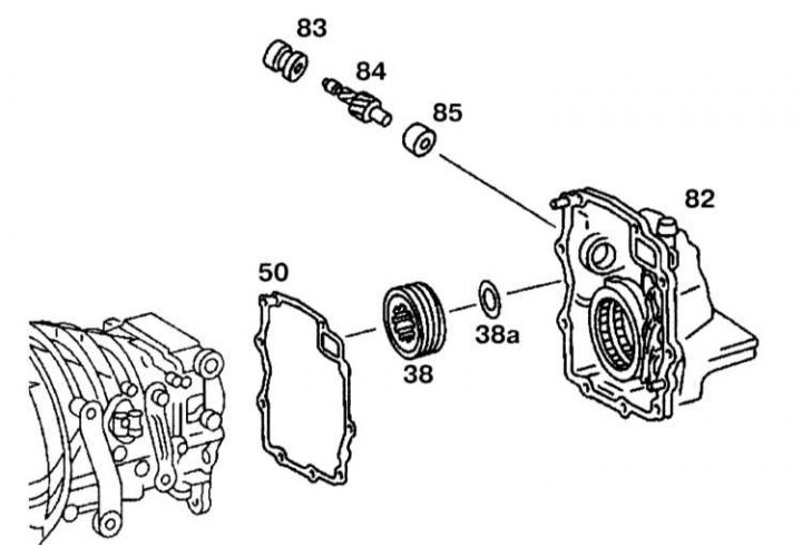
Installation Details of Mechanical Type VSS
38 - Helical speedometer gear; 38a - Thrust washer; 50 - Sealing gasket; 82 - Rear cover of the gearbox; 83 - Radial oil seal; 84 - Speedometer drive gear; 85 - Sealing cap
1. Remove the gearbox rear cover.
2. Remove the sealing cap (85).
3. Remove the speedometer drive gear (84).
4. Remove the radial oil seal (83).
5. Remove the helical gear (38) and thrust washer (33a).
Installation
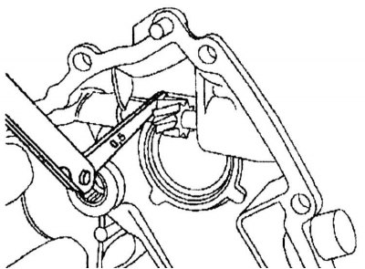
Checking the clearance between the drive gear and the gearbox cover
Installation is carried out in the reverse order of removal. The gap between the drive gear and the gearbox cover is 0.5 mm.