Contents: Leading and driven gears of manual…↡ Leading and driven gears of manual…↡ Leading and driven gears of manual…↡
Leading and driven gears of manual transmission up to No.0210417
Removal
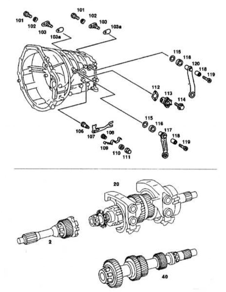
Leading and driven gears of the gearbox up to No.0210417
2 - Drive shaft; 20 - Driven shaft; 40 - Intermediate shaft; 101, 114, 119 - Bolts; 102, 103a, 110, 112 - Gaskets; 103 - Shaft; 106 - Finger; 107 - Locking lever; 108, 118 - Bushing; 109 - Locking leaf spring; 111 - Nut; 113 - Locking bearing; 115 - Sealing ring; 116 - Lid; 117 - 3/4th gear engagement lever; 120 - 1/2 gear engagement lever
1. Remove the locking bearing (113).
2. Remove the gear shift lever (117) and 1/2 gear shaft (103).
3. Remove the driven shaft (20) from the gearbox housing.
4. Remove the gear shift lever (120) and 3/4th gear shaft (103).
5. Remove the lever with the fork and the 3/4th gear shift clutch.
6. Remove the intermediate shaft (40) from the gearbox housing.
7. Remove the drive shaft (2) with the tapered roller bearing and 4th gear synchronizer ring.
8. Using a punch, knock out the outer races of the intermediate and drive shaft bearings from the gearbox housing.
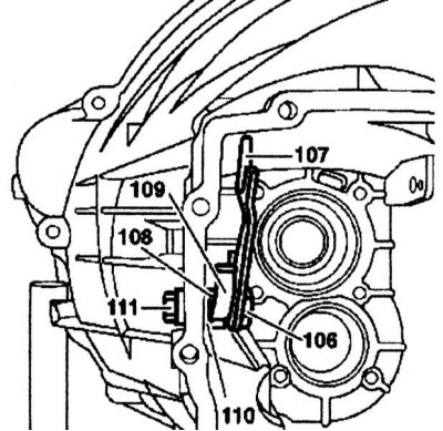
9. Unscrew the nut (111), press out and remove the pin (106) with the locking leaf spring (109), the locking lever (107), the bushing (108) and the gasket (110).
Installation
1. Install the locking lever (107), locking leaf spring (109), bushing (108) and gasket (110) onto the pin (106). Press the pin (106) through the gearbox housing from the inside and secure it with a new nut (111).
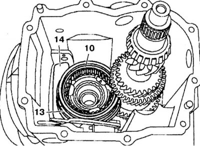
2. Install the intermediate shaft (40) into the gearbox housing. 3. Fasten the coupling (10) with the fork (13) and lever (14) to the drive shaft and synchronizer so that the groove in the coupling (10) faces upward.
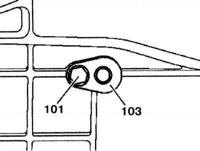
4. Insert the 3/4 gear engagement shaft (103) into the gearbox housing. Lubricate the bolt (101) with sealant and screw it in.
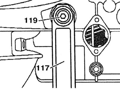
5. Insert the 3/4 gear engagement lever (117) so that it engages with the splines of the gear shift lever. Insert the bushing (118), lubricate the bolt (119) with sealant and tighten it.
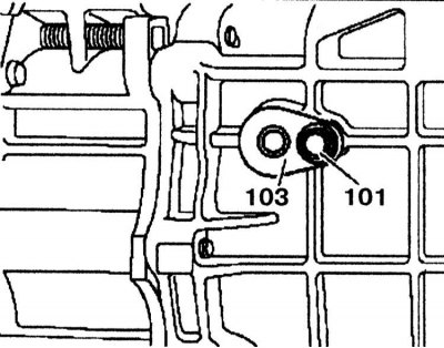
6. Insert the drive shaft (20) into the gearbox housing. 7. Install the 1/2-gear engagement shaft (103) into the gearbox housing (101), lubricate it with sealant, and tighten the mounting bolt.
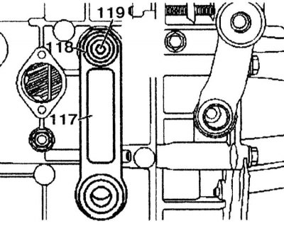
8. Install the 3/4 gear engagement lever (117) so that it engages with the splines of the gear shift lever. Insert the bushing (118), lubricate the bolt (119) with sealant and tighten it.
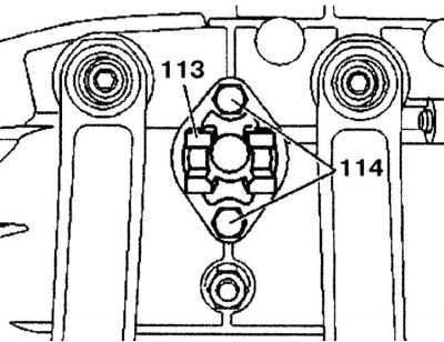
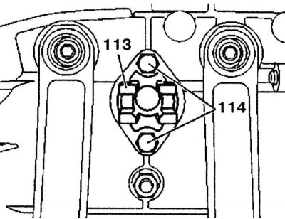
9. Insert the locking bearing (113) into the gearbox housing so that one ball is positioned downwards towards the nut.
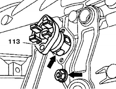
10. Tighten the locking bearing (113) with the bolt (114).
(Information copied from the website: www.mercedesman.ru)
Leading and driven gears of manual transmissions from No.0210418 to No.6141000
Removal
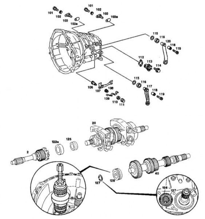
Leading and driven gears of manual transmissions from No.0210418 to No.6141000
2 - Drive shaft; 20 - Driven shaft; 40 - Intermediate shaft; 101, 114, 119 - Bolts; 102, 103a, 110, 112, 122, 123 - Gaskets; 106 - Finger; 107 - Locking lever; 108, 118 - Bushing; 109 - Locking leaf spring; 111 - Nut; 113 - Locking bearing; 115 - Sealing ring; 116 - Lid; 117 - 3rd/4th gear shift lever; 120 - 1st/2nd gear shift lever; 121 - Spring; 124 - Thrust bearing; 125 - Needle bearing; 126 - Disc; 127 - Retaining ring; 128 - Ball bearing
1. Remove the locking bearing (113).
2. Remove the gear shift lever (117) and 1/2 gear shaft (103).
3. Remove the driven shaft (20) from the gearbox housing.
4. Remove the gear shift lever (120) and 3/4th gear shaft (103).
5. Remove the intermediate shaft (40) from the gearbox housing.
6. Remove the drive shaft (2) with the tapered roller bearing and 4th gear synchronizer ring.
7. Remove the needle bearing (125) and disc (126) from the drive shaft (2).
8. Remove the needle bearing (125), thrust bearing (124), shims (122), (123) and spring (121) from the drive shaft.
9. Remove the outer bearing race from the intermediate and drive shafts using a drift.
10. Unscrew the nut (111), press out and remove the pin (106) with the locking leaf spring (109), the locking lever (107), the bushing (108) and the gasket (110).
Installation
1. Install the locking lever (107), locking leaf spring (109), bushing (108) and gasket (110) onto the pin (106). Press the pin (106) through the gearbox housing from the inside and secure it with a new nut (111).
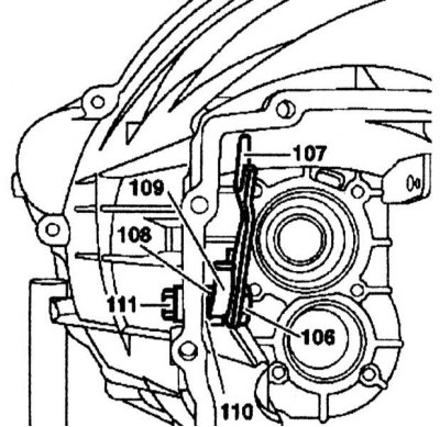
2. Using a drift, carefully tap the outer bearing race until it protrudes approximately 2mm (for intermediate shaft) and 6 mm (for the drive shaft).
3. Insert the drive shaft (2) with the tapered roller bearing and synchronizer for engaging 4th gear into the gearbox housing.
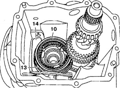
4. Install the intermediate shaft (40) into the gearbox housing 5. Fasten the clutch (10) with the fork (13) and lever (14) to the drive shaft and synchronizer so that the groove in the clutch (10) is facing upwards.
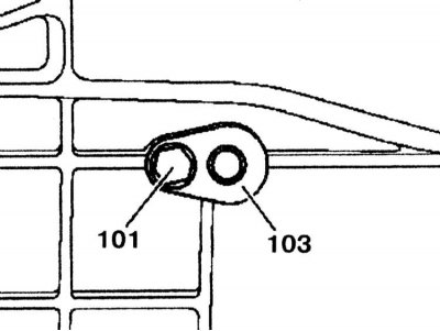
6. Insert the 3/4 gear shift shaft (103) into the gearbox housing. Coat the bolt (101) with sealant and screw it in.
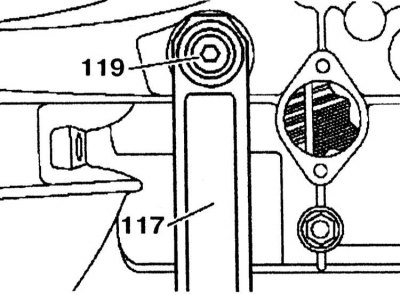
7. Insert the 3/4 gear engagement lever (117) so that it engages with the splines of the gear shift lever. Insert the bushing (118), lubricate the bolt (119) with sealant and tighten it.
8. Insert the driven shaft (20) into the gearbox housing.
9. Install the 1/2 gear engagement shaft (103) into the gearbox housing, lubricate it with sealant, and tighten the mounting bolt (101).
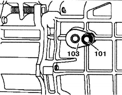
10. Install the 3/4 gear engagement lever (117) so that it engages with the splines of the gear shift lever. Insert the bushing (118), lubricate the bolt (119) with sealant and tighten it.
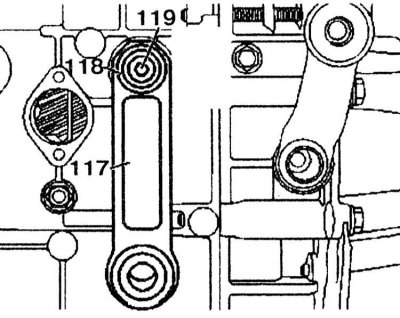
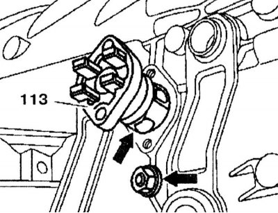
11. Insert the locking bearing (113) into the gearbox housing so that one ball is positioned downwards towards the nut.
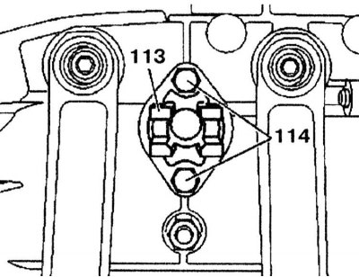
12. Tighten the locking bearing (113) with the bolts (114).
Leading and driven gears of manual transmission with No.6141001
Removal
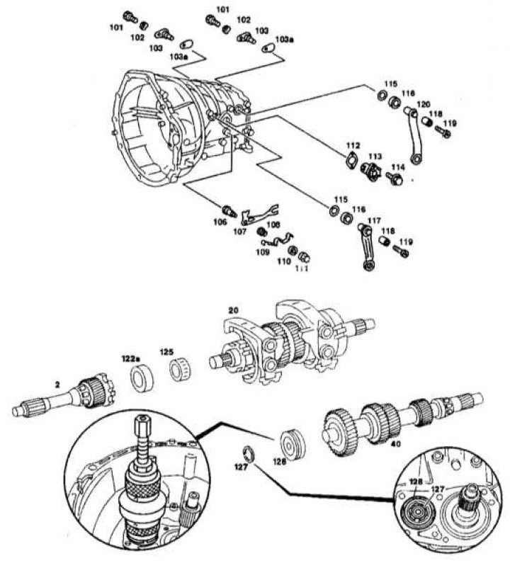
Leading and driven gears of manual transmission with No.6141001
1a, 128 - Ball bearings; 1b, 127 - Retaining rings; 2 - Drive shaft; 20 - Driven shaft; 40 - Intermediate shaft; 101, 114, 119 - Bolts; 102, 103a, 110, 112, 122, 123 - Gaskets; 103 - Shaft; 106 - Finger; 107 - Locking lever; 108, 118 - Bushings; 109 - Locking leaf spring; 111 - Nut; 113 - Locking bearing; 115 - Sealing ring; 116 - Lid; 117 - 3rd/4th gear shift lever; 120 - 1st/2nd gear shift lever; 121 - Spring; 122a - Bushing; 125 - Needle bearing; 127 - Retaining ring; 128 - Ball bearing
1. Remove the locking bearing (113).
2. Remove the shift lever (117) and shaft (103) of 1/2 gear.
3. Remove the retaining ring (127) of the ball bearing (128) of the intermediate shaft (40).
4. Remove the front ball bearing (128) from the intermediate shaft (40).
5. Remove the driven shaft (20) from the gearbox housing.
6. Remove the shift lever (120) and shaft (103) of 3/4th gear.
7. Remove the lever with the fork and the 3/4th gear shift clutch.
8. Remove the intermediate shaft (40) from the gearbox housing.
9. Remove the drive shaft (2) from the gearbox housing.
10. Remove the needle bearing (125) and sleeve (122a) from the drive shaft (2).
11. Unscrew the nut (111) and remove the pin (106) with the locking leaf spring (109), the locking lever (107), the bushing (108) and the gasket (110).
Installation
1. Install the locking lever (107), locking leaf spring (109), bushing (108) and gasket (110) onto the pin (106). Press the pin (106) through the gearbox housing from the inside and secure it with a new nut (111).
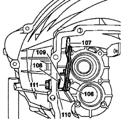
2. Fasten the needle bearing (125) and sleeve (122a) to the drive shaft (2). 3. Press the ball bearing (1a) onto the drive shaft (2), install the retaining ring (1b) and install the drive shaft (2) into the gearbox housing.
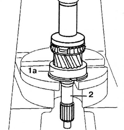
4. Install the intermediate shaft (40) into the gearbox housing.
5. Fasten the coupling (10) with the fork (13) and lever (14) to the drive shaft and synchronizer so that the groove in the coupling (10) is facing upwards.
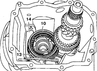
6. Insert the 3/4 gear shift shaft (103) into the gearbox housing. Coat the bolt (101) with sealant and screw it in.
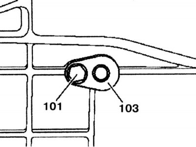
7. Insert the 3/4 gear engagement lever (117) so that it engages with the splines of the gear shift lever. Insert the bushing (118), lubricate the bolt (119) with sealant and tighten it.
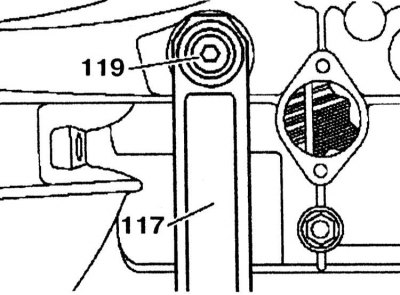
8. Insert the drive shaft (20) into the gearbox housing.
9. Install the 1/2-gear engagement shaft (103) into the gearbox housing. Lubricate the bolt (101) with sealant and screw it in.
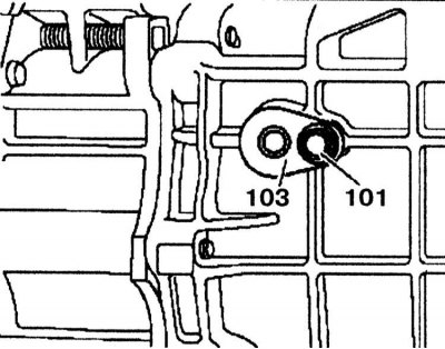
10. Install the 3/4 gear engagement lever (117) so that it engages with the splines of the gear shift lever. Insert the bushing (118), lubricate the bolt (119) with sealant and tighten it.
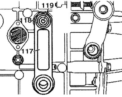
11. Screw press 124 589 0931 00 onto the intermediate crankcase and secure the intermediate shaft with bolts.
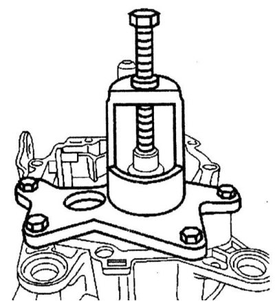
12. Press the ball bearing (128) into the bearing seat on the intermediate shaft using press 124 589 00 15 00. Move the press mounting bolts 124 589 09 31 00 back on the intermediate shaft by approximately 2 cm. Press the ball bearing (128) into the gearbox housing until it stops.
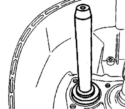
13. Install the retaining ring (127).
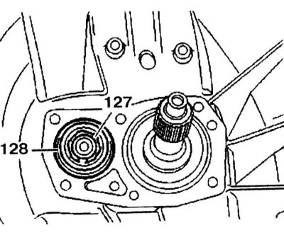
14. Insert the locking bearing (113) into the gearbox housing so that one ball is positioned downwards towards the nut.
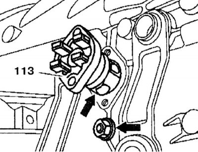
15. Tighten the locking bearing (113) with the bolts (114).