



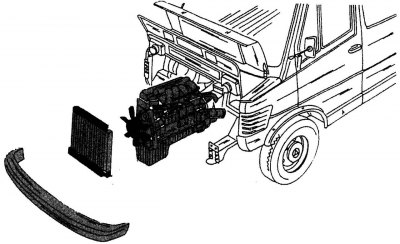
Figure 14. Dismantling the power unit
To dismantle the power unit, a lifting hoist or hand winch is required. The power unit is removed forward after removing all the parts shown in the figure There are 14 parts to the front of the car, which is a lot of work. It should be remembered that its weight is approximately 200 kg, so the recommended chain hoists or hand-operated lifting winches must be able to withstand this load. Since it is very difficult to remove the power unit by lifting it upward, a manual crane with an extendable boom is best suited for this job. The following instructions apply to all engine types.
Below are described all the most important stages of dismantling the power unit, however, some cars may be equipped with additional connections that will need to be disassembled and which are not indicated in the description. In the driver's cabin, all that is required is to disconnect the gearshift lever from the gearbox. The power unit is removed forward after dismantling the front parts of the vehicle.
The power unit must be dismantled as follows:
- open the hood and tilt it completely onto the windshield. To do this, you need to disconnect the support at the top of the hood. Before doing this, you need to put some old blanket on the windshield;
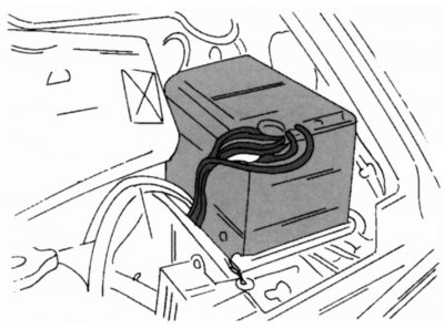
Figure 15. Location of the battery in the engine compartment (left front)
- disconnect both terminals of the battery (to avoid a short circuit, disconnect the negative terminal first!). The battery is located in the front part of the engine compartment (figure 15). To avoid accidentally dropping the tool on the battery terminals and causing sparks, it is recommended to remove the battery from the engine compartment;
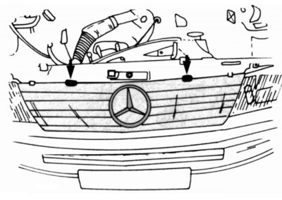
Figure 16. Removing the radiator grille (arrows point to the grille mounting bolts)
- remove the radiator grille. To do this, unscrew the two bolts indicated by the arrows in the figure 16. After this, the grate can be easily pulled out, folding forward;
- remove the radiator cap. In this case, the coolant temperature should not be higher than 50°C. Drain the coolant from the engine cooling system according to the instructions contained in subsection 4.1;
- remove the radiator following the instructions in the relevant chapter;
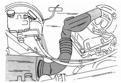
Figure 17. Removing the air duct connecting the air filter and the intake manifold (on a 2.3 liter engine)
- remove the air duct connecting the air filter and the intake manifold (shown in the figure17 on a 2.3L engine);
- remove the front bumper and radiator mounting support bar;
- disconnect the exhaust pipe from the exhaust manifold and gearbox;
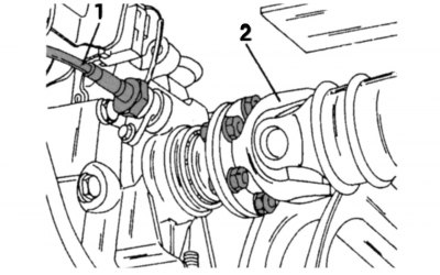
Figure 18. Location of the tachometer drive on the gearbox: 1 - tachometer drive; 2 - cardan shaft
- disconnect the propeller shaft from the gearbox output shaft flange and unscrew the tachometer drive (figure 18);
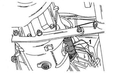
Figure 19. Location of the clutch release slave cylinder (1) on the gearbox
- remove the clutch release slave cylinder from the gearbox and, without disconnecting the hoses, move it to the side. Use a piece of wire to secure it under the car so that it does not hang on the hoses. Figure 19 shows the location of the slave cylinder on the gearbox;
- disconnect the ground wire;
- disconnect the electrical wiring from the starter and alternator. Disconnect all electrical wiring harnesses from the engine and move them to the side so that they do not get mixed up later during assembly;
- disconnect the wiring from the glow plug relay;
- disconnect all vacuum lines from the engine;
- remove the drive belt following the instructions in the relevant section;
- unscrew the three bolts securing the power steering pump drive pulley and remove the pulley from the pump hub;
- remove the power steering pump and, without disconnecting the hoses, move it to the side;
- disconnect the fuel lines from the coarse filter and close them to prevent dirt from getting inside;
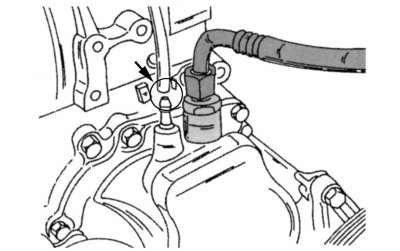
Figure 20. Disconnecting the brake booster vacuum hose from the vacuum pump nipple
- remove the vacuum hose from the vacuum pump nipple as shown in the figure 20. This hose connects the pump to the brake booster;
- remove the handle from the gear shift lever, remove the rubber seal and pull the lever out of the gearbox after loosening the locking screw (see also section. "Transmission");
- loosen the mounting clamp and remove the heater hose from the thermostat housing;
- remove starter;
- disconnect the oil lines from the oil filter housing;
- disconnect the gearbox mount to the crossmember (one nut);
- disconnect the fastenings of both engine mounts (on both sides under the car);
- roll a hand crane with a boom at the front into the engine compartment and secure its cable or chain slings to the lifting eyes on the engine. At the same time, place a dolly under the rear of the power unit at the junction of the engine and gearbox to support the unit from below. Now, before continuing with the work of dismantling the engine and gearbox mounts, you should make sure that the power unit is securely held by the lifting devices and will not fall off them;
- disconnect the fuel mixture supply control rods;
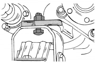
Figure 21. Gearbox suspension mount
Full article available on the resource www.MercedesMan.ru
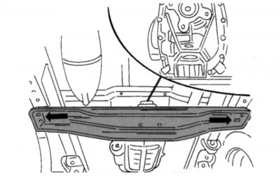
Figure 22. Fastening the rear crossmember of the gearbox to the side members of the car
- disconnect the fasteners of the gearbox and engine crossmembers. Figures 21 and 22 show how these parts are secured. Before disassembling the crossbar fasteners, be sure to once again ensure that the power unit is securely suspended and held in the lifting devices;
- turn the power unit slightly to the side so that the gear shift lever mounting protrusion does not catch on the lower part of the body, and pull or roll the unit out on a dolly from the engine compartment of the car. Try not to touch the steering parts.