
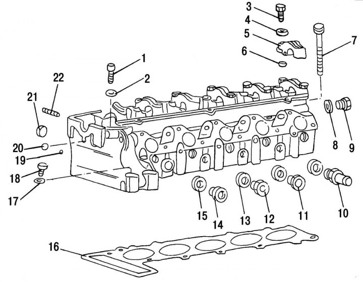
Pic. 34. 2.9L Engine Cylinder Head Parts: 1 - cylinder head bolt located in the drive chain housing; 2 - elastic washer; 3 — a bolt of fastening of a cover of the bearing to a head of the block of cylinders; 4 — a washer of a bolt of fastening of a cover of the bearing; 5 - camshaft bearing cover; 6 - landing sleeve; 7 — a bolt of fastening of a head of the block of cylinders; 8 - sealing ring; 9 - rear plug of the oil channel; 10 - fitting for connecting the heater pipes; 11 - threaded adapter; 12 — adapter for temperature sensor connection; 13 - sealing ring; 14 — adapter for temperature sensor connection; 15 - sealing ring; 16 - cylinder head gasket; 17 — a washer of a bolt of fastening of the fuel filter to a head of the block of cylinders; 18 — a bolt of fastening of the fuel filter to a head of the block of cylinders; 19 - a ball for closing the channels of the cooling system; 20 - a ball that closes the oil channel in front; 21 - cork; 22 — a hairpin of fastening of a final collector
- remove all parts from the cylinder head (pic. 34);
- remove the camshaft. To do this, unscrew all the bolts securing the camshaft bearing caps, after which the shaft can be separated from the cylinder head. Numbers are stamped on the bearing caps, which must match the numbers stamped on the cylinder head;
- A special valve puller is required to remove the valves. For this purpose, any device that can compress the valve spring by acting on its upper plate can fit. After compressing the valve spring, remove the crackers with tweezers or a magnet. If there are no special tools for compressing the valve springs, then the cylinder head should be placed on a smooth and even surface of the workbench so that the valves are supported from below. After that, take a piece of pipe with a diameter smaller than the diameter of the upper plate of the valve spring, put it on the upper plate of the valve spring and hit the upper end of the pipe with a hammer. In this case, crackers will jump out of the cone of the plate and remain inside the pipe. When hitting, do not lift the hammer above the pipe so that the crackers do not jump out and get lost;
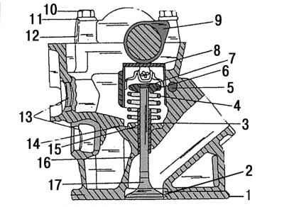
Pic. 35. Cylinder head and intake valve: 1 - cylinder head; 2 - inlet valve seat; 3 - oil deflector cap; 4 - valve spring; 5 - oil line; 6 - the upper plate of the valve spring; 7 - crackers; 8 - valve lifter with hydraulic clearance compensator (hydropusher); 9 - camshaft; 10 - M8x45 bolt for fastening the camshaft bearing cover; 11 - washer; 12 - camshaft bearing cap; 13 - plugs of the cylinder head; 14 - thrust ring of the valve spring; 15 - retaining ring; 16 - guide sleeve of the intake valve; 17 - inlet valve
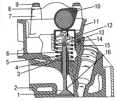
Pic. 36. Cylinder head and exhaust valve: 1 - exhaust valve seat; 2 - cylinder head; 3 - retaining ring; 4 - thrust ring of the valve spring; 5 - exhaust valve guide sleeve; 6 - oil cap; 7 — a cover of the bearing of a camshaft; 8 - washer; 9 - M8x45 bolt of the camshaft bearing cover; 10 - camshaft; 11 - valve lifter with hydraulic clearance compensator (hydropusher); 12 - crackers; 13 - retaining ring; 14 - oil channel; 15 - valve spring; 16 - exhaust valve
- Remove upper valve spring retainers and valve springs. Each valve has one color-coded spring. When reassembling, valve springs with the same marking must be used. Remove the lower valve spring retainers. On fig. 35 and 36 show the valves mounted on the engine;
- using a screwdriver or pliers, carefully remove the valve stem seals;
- pull the dry valves out of the guide bushings and place them on a piece of cardboard with the appropriate marking of the number of each valve.