



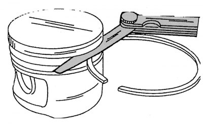
Figure 58. Measuring vertical clearances in piston ring grooves using a feeler gauge
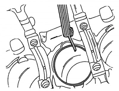
Figure 59. Measuring gaps in piston ring locks located in engine cylinders
Conduct a thorough inspection of all parts. If there are any burrs, scratches or signs of wear, replace them with new ones. Measure the vertical clearance in the piston ring grooves using a feeler gauge inserted between the plane of the piston ring and the plane of the piston ring groove, as shown in the figure 58 (the grooves must be thoroughly cleaned before this, for this you can, for example, use a broken piston ring). If the measurement results show that the gaps in the upper rings exceed 0.20 mm, in the middle rings - 0.15 mm and in the oil scraper rings - 0.10 mm, then this indicates wear of the piston rings or pistons. Then, from the inside of the engine crankcase, it is necessary to insert the piston rings into the cylinder holes one by one, and with the inverted piston on top, move them down so that they are positioned horizontally and are at a distance of 20 mm from the lower edge of the cylinder liners. Then use a feeler gauge to measure the gaps in the piston ring locks, as shown in the figure 59. On all rings this gap is 0.20–0.40 mm. The maximum permissible wear for the locks of the upper rings should not exceed 1.5 mm, for the remaining rings – 1.0 mm.
Check the piston pins and connecting rod bushings for wear and scoring. In this case, a single replacement of the faulty connecting rod is allowed, however, the weight of the new connecting rod should not differ from the weight of the connecting rod being replaced by more than 5 g. We recommend replacing the bushings in the upper heads of the connecting rods at specialized service stations.
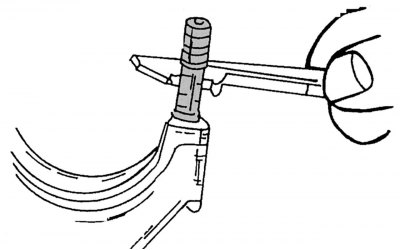
Figure 60. Measuring the diameters of the flexible part of the connecting rod bearing cap fastening bolts
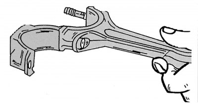
Figure 61. Checking the crank for ease of movement
Before reusing the connecting rod bearing cap bolts, it is necessary to measure the diameters of their thin parts using a caliper (figure 60). If the measured diameters of the bolts are less than 7.1 mm, then such bolts must be replaced, which should be carried out in accordance with the instructions below. Before replacing the bolts, one more check should be performed, which consists of the following: the connecting rod bearing cap is seated on one bolt and turned to the side so that the connecting rod and the bearing cap turned to the side are on the horizontal axis, as shown in the figure 61. If the bearing cap falls down under its own weight, then this connecting rod must be replaced with a new one. Otherwise, the bolts must be replaced. In the connecting rod testing device, all connecting rods should be checked for twisting and bending, the values of which should not exceed the minimum permissible values. It is also recommended to contact a specialized service station to perform this work. When checking pistons and connecting rods, the following recommendations exist.
It is not recommended to reuse connecting rods that have once been overheated due to bearing failure (connecting rods with tempered color).
The connecting rods and connecting rod bearing caps are matched to each other and marked.
Original article is on the portal MERCEDESMAN
New connecting rods are supplied with bored bushings in the upper heads and can be installed directly into the engine.
Install the connecting rod bearing caps with liners onto the bolts and measure the inner diameter of the bearings using a bore gauge. If the obtained result exceeds the value of 51.619 mm or some taper is detected, then the bearing surface of the connecting rod bearing cap can be adjusted on a flat plate up to 0.02 mm.

Figure 62. Connecting rod: 1 — connecting rod upper head bushing; 2 — connecting rod; 3 - upper bearing shell; 4 - elastic clamping pins; 5 — lower bearing shell; 6 — connecting rod bearing cap bolt; L=145 mm; B=24.0 mm; D=47.95 mm; D1=29.50 mm; D2=26.0 mm (tolerance 0.018–0.024 mm)
If the connecting rod is in perfect condition, but an increased gap is found in the piston pin, then it is necessary to replace the bushing in the upper head of the connecting rod by pressing out the old one and pressing in a new one. In this case, it is necessary to pay special attention to the location of the oil hole in the bushing. It should be in line with the arrow shown in the figure 62. After pressing the new bushing into the upper head of the connecting rod, it must be expanded to the diameter D2 indicated in the figure 62. This figure shows the permissible diameter.