
Attention! Each time a connecting flange is removed, the resistance to rotation of the associated axle assembly must be measured (without wheels), - the brakes must be released.
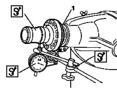
Checking the concentricity of the connecting flange (1) final drive gear
Connecting flange installation details
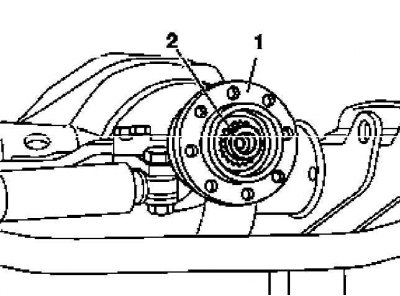
1 - Connecting flange
2 - Flanged nut
1. Detach from the flange (1) cardan shaft, take it aside and tie it with a wire to the car frame, - the procedure for performing the procedure is similar to that described in Section Disconnection and connection of cardan shafts on the transfer case for connecting flanges of the transfer case.
2. Checking is done using a plunger-type dial gauge (DTI) and a special adapter flange (460 589 01 23 00).
3. Connect the adapter flange to the connecting (1).
4. Fix the meter frame on the axle housing in such a way that its plunger is pressed against the measuring surface of the front trunnion of the adapter flange.
5. Zero the instrument and take the required reading by turning the main gear one full turn. Compare the measurement result with the requirements Specifications.
Front axle
If there is play in the front axle final drive flange, replace the flange.
Attention! In order to avoid damage to the bearings, in no case knock down the flange with a hammer - if necessary, use a special puller (460 589 02 33 00)! The flanged nut must be replaced without fail!
Rear axle
1. If the rear axle flange play exceeds the limit, unlock and loosen the flange nut (2) and remove the flange, having previously marked the position of the nut and flange relative to the pinion shank.
Attention! In order to avoid damage to the bearings, in no case knock down the flange with a hammer - if necessary, use a special puller (460 589 02 33 00)!
2. Assess the condition of the flange, if necessary, replace it.
3. If no replacement is necessary due to damage, turn the flange 180°clockwise, reinstall, and recheck. Further, if necessary, the flange can be deployed two more times (90°and again 180°). If it is not possible to achieve the desired result by expanding the flange, replace it.
4. Ensure that the flanged nut (in case of refusal to replace it) was tightened until the landing marks applied during the dismantling were combined.
Both bridges
1. Reattach the propeller shaft and secure it with NEW self-locking nuts, tightening the latter to the required torque.