
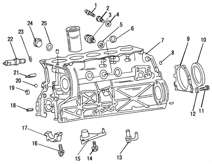
Pic. 65. Parts installed on the cylinder block: 1 - connecting fitting; 2 - threaded nozzle; 3 - connecting fitting for draining the coolant, on the right side; 4, 5 - sealing rings; 6 — a cap of the block of cylinders; 7 - cylinder block; 8 - a ball blocking the oil line at the back; 9 — a flange of a back cuff of a cranked shaft; 10 — a back cuff of a cranked shaft; 11 — a bolt of fastening of a flange of a back cuff of a cranked shaft to the block of cylinders; 12 - elastic washer; 13 - oil spray nozzle of the piston cooling system, new design; 14 — a bolt with a six-sided head; 15 - oil spray nozzle of the piston cooling system, obsolete; 16 — a bolt of fastening of a cover of the radical bearing; 17 - main bearing cap; 18 - landing sleeve of the cover of the camshaft drive mechanism; 19 - plug for closing the oil channel in front; 20 - a ball that locks the oil line in front; 21 - fitting for connecting the lubricant supply pipe to the chain; 22 - a tube for supplying lubricant to the chain; 23 - sealing ring of the oil spray nozzle on the block; 24 - screw plug on the left side; 25 - sealing ring
On fig. 65 shows a 2.9 liter diesel engine block in disassembled condition with the designation of the removed parts. When completely disassembling the cylinder block, it is necessary to thoroughly clean all cavities and oil channels, removing deposits and foreign particles.
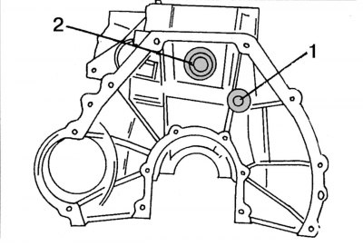
Pic. 66. Rear of the cylinder block showing the location of the steel ball (1), blocking the main oil line, and plugs (2) cylinder block
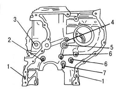
Pic. 67. The front of the cylinder block: 1 - spring tension pin; 2 — a basic finger of a chain damper; 3 - steel ball with a diameter of 17 mm; 4 - oil spray nozzle; 5 — a cap of the block of cylinders; 6 - support pin of the chain tensioner shoe; 7 — a basic finger of a natnitel of a chain of a drive of the oil pump
Particular care must be taken to ensure that the flushing liquid is completely removed. Be sure to blow out all cavities and channels with compressed air. The main oil channel is closed from the end sides with steel balls with a diameter of 17 mm from the front side and a diameter of 15 mm from the rear side of the cylinder block. For a more thorough cleaning of the main oil line, these balls must be removed. Balls can be reused if their surfaces show no visible damage. The location of these balls is shown in Fig. 66 and 67. In addition, in fig. 67 shows the details of the cylinder block, which should also be carefully checked for signs of wear. For the subsequent installation of balls that block the oil channel to the desired depth, a special mandrel is required, included in the specification of spare parts under the number 601 589 08 15 00.
Note. If oil leaks occur from under the balls on the front or rear sides of the cylinder block and if it is not possible to purchase the above-mentioned special mandrel, the oil channels can be blocked with screw plugs. A plug M18x1.5mm is screwed in from the front (spare parts specification number - 000906 018 000), and on the back side - cork M16x1.5mm (spare parts specification number - 000906 016 002). Beforehand, the corresponding threads must be cut in the channels of the cylinder block: from the front side to a depth of 10 mm, and from the rear side to a depth of 14 mm. After cutting the thread, clean the channels from the remaining chips. Lubricate the threaded portion of the rear plug with Loctite before tightening. Tightening torque 50 Nm.
If it is planned to replace the steel balls with new ones without removing the engine from the vehicle, then the following work must be done:
- remove the oil pump;
- remove the gearbox and flywheel;
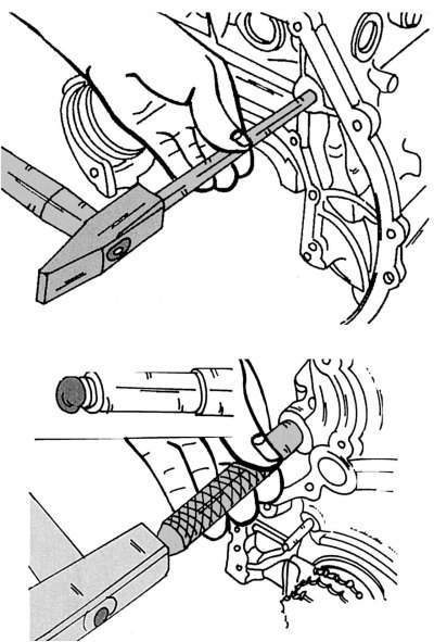
Pic. 68. Pressing the steel ball out of the cylinder block (up) and its subsequent installation (at the bottom)
- knock out the balls using a steel rod with a diameter of 14 mm and a length of 550 mm from the back side, as shown in fig. 68;
- thoroughly clean the oil channel;
- lubricate the spherical recess of the special mandrel with grease and insert a ball into it;
- insert the mandrel with the ball into the corresponding hole in the oil channel and press the ball in until it stops (see fig. 68, bottom);
- install the oil pump, flywheel, gearbox and start the engine. Inspect the engine for oil leaks.