



- conduct a thorough inspection of the crankshaft for wear and deformation, measure the journals of the main and connecting rod bearings. The crankshaft journals can be ground four times, so the crankshaft can be installed with oversize liners;
- clamp the crankshaft on a lathe (or place it on prisms placed under the outer journals of the main bearings) and check the runout on the middle main journal using a measuring indicator. The runout should not exceed 0.06 mm, otherwise the crankshaft must be replaced.
- The clearance in the main and connecting rod bearings must be measured in the following order:
- install the corresponding covers without liners on the bearing seats of the cylinder block, lubricate the threaded parts of the fastening bolts and tighten the bolts alternately, first with a force of 55 N·m, and then turn them by 90–100°. The main bearing caps are made with some offset, so they can only be installed in one, correct position;
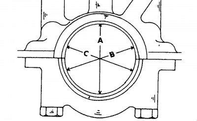
Figure 77. Measuring the crankshaft bearing holes
- measure the diameter of each bearing in the direction of axes A, B, C, indicated in the figure 77, and record the results. If any of the measurement results exceeds the other or a conical wear of the bearing bore is detected, the cover of such a bearing can be finished with sandpaper within a range of no more than 0.02 mm;
- remove all main bearing caps, install the liners, which must first be thoroughly cleaned, and then install the bearing caps with the liners and tighten the bearing cap mounting bolts properly (see above);
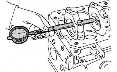
Figure 78. Measuring the inner diameter of bearing shells using a bore gauge
- measure the diameter of each bearing as shown in the figure 78, and record the measurement results;
- the obtained values of the bearing diameters with the installed liners should be subtracted from the values of the crankshaft main journal diameters. The obtained results will indicate the working clearances, which should not be within the range of 0.0310.073 mm for both main and connecting rod bearings of the crankshaft. The wear limit is 0.080 mm. If necessary, these gaps can be adjusted by installing liners of different repair sizes. Mercedes-Benz offers crankshaft bearing shells in four repair sizes. The remaining works do not differ significantly from each other and are described above.
Below are recommendations for selecting main bearing shells.
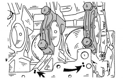
Figure 79. Designation of crankshaft main bearing bore tolerances (shown by arrows)
The crankshaft main bearing shells are selected and installed in accordance with the markings made with a center punch near the bearing seats in the cylinder block. The location of the markings is shown by arrows in the figure 79. The side edges of the liners are marked with the appropriate color (see below). This marking must be followed, although it should be noted that only liners with green or red markings are offered for repair.
The liners are installed in the main bearing caps taking into account the diameter of the crankshaft main journals. For this reason, each shaft knee is color-coded (blue, green or red dot):
| Neck diameter, mm | Number of points scored | Color marking |
| 62,500–62,506 | 1 | blue |
| 62,506–62,513 | 2 | green |
| 62,513–62,519 | 3 | red |
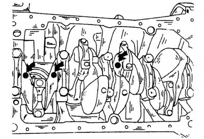
Figure 80. Color marking applied to each shaft knee
Material taken from a web resource (mercedesman.ru)
The location of the marking is indicated by arrows in the figure 80.