
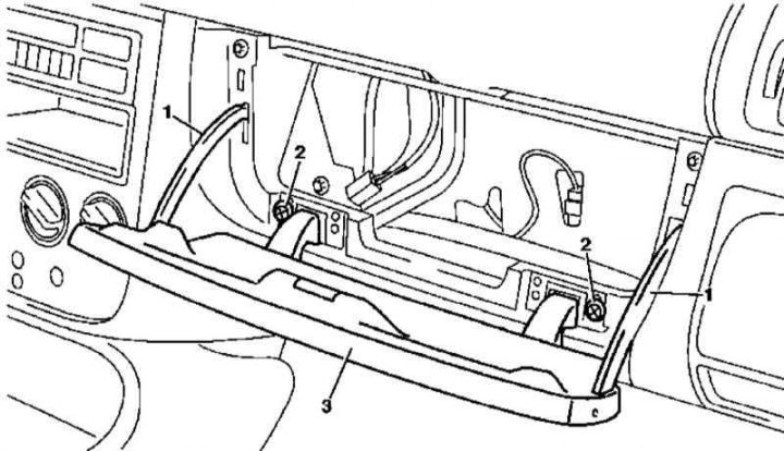
Main glove box cover installation details
1. The installation details of the main glove box cover are shown in the illustration, to which all references in the text refer.
2. Remove the glove box (see Section Removal and installation of the main glove box).
3. Slightly lift the lid (3) and release the lock levers (1).
4. Remove the cover (3).
5. Installation is carried out in the reverse order.
Adjustment (models 163.136/154/172 with VIN according to A145272, X708318)
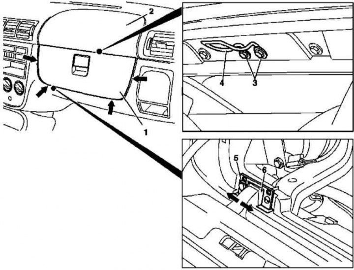
Glove box lid adjustment (models 163.136/154/172 with VIN according to A145272, X708318)
Arrows - Cover clearance
1. The relevant illustrative material is presented in the illustration, which includes all references in the text.
2. Loosen the screws (3) drummer mounts (4) and correct the position of the latter so that in the closed position the lid (1) slightly pressed against the buffer stops.
3. If necessary, se box (see Section Removal and installation of the main glove box) and loosen the bolts (5), adjust the position of the loops (6), achieving a uniform lid fit gap (1) in the instrument panel (2).
4. Check up freedom of a course of a cover and serviceability of a latch of the lock.
5. Replace the drawer (see Section Removal and installation of the main glove box).